
Instruction Manual

GE
Data Sheet
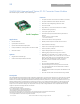
SHHD003A0A Hammerhead
Series; DC-DC Converter Power Modules
18-75Vdc Input; 5.0Vdc, 3A, 15W Output
June 26, 2013 ©2012 General Electric Company. All rights reserved. Page 7
Feature Description
Remote On/Off
Two remote on/off options are available. Positive logic turns
the module on during a logic high voltage on the on/off pin,
and off during a logic low. Negative logic remote on/off, device
code suffix “1”, turns the module off during a logic high and on
during a logic low.
ON/OFF
Vin+
Vin-
I
on/off
V
on/off
Vout+
TRIM
Vout-
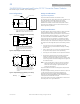
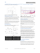
Figure 10. Circuit configuration for using Remote On/Off
Implementation.
To turn the power module on and off, the user must supply a
switch (open collector or equivalent) to control the voltage
(V
on/off
) between the ON/OFF terminal and the V
IN
(-) terminal.
Logic low is 0V ≤ V
on/off
≤ 0.8V. The maximum I
on/off
during a
logic low is 1mA, the switch should be maintain a logic low
level whilst sinking this current.
During a logic high, the typical V
on/off
generated by the module
is 2.4V, and the maximum allowable leakage current at V
on/off
=
2.4V is 25μA.
If not using the remote on/off feature:
For positive logic, leave the ON/OFF pin open.
For negative logic, short the ON/OFF pin to V
IN
(-).
Overcurrent Protection
To provide protection in a fault (output overload) condition, the
unit is equipped with internal current-limiting circuitry and can
endure current limiting continuously. At the point of
current-limit inception, the unit enters hiccup mode. The unit
operates normally once the output current is brought back into
its specified range. The average output current during hiccup
is 10% I
O, max
.
Overtemperature Protection
To provide protection under certain fault conditions, the unit is
equipped with a thermal shutdown circuit. The unit will
shutdown if the thermal reference point Tref (Figure 16),
exceeds 125
o
C (typical), but the thermal shutdown is not
intended as a guarantee that the unit will survive
temperatures beyond its rating. The module will automatically
restart upon cool-down to a safe temperature.
Input Undervoltage Lockout
At input voltages below the input undervoltage lockout limit,
the module operation is disabled. The module will only begin
to operate once the input voltage is raised above the
undervoltage lockout turn-on threshold, V
UV/ON
. Once
operating, the module will continue to operate until the input
voltage is taken below the undervoltage turn-off threshold,
V
UV/OFF
.
Over Voltage Protection
The output overvoltage protection consists of circuitry that
independently monitors the output voltage, and shuts the
module down if the output voltage exceeds specified limits.
The module shall contain hiccup restart capability.
Output Voltage Programming
Trimming allows the user to increase or decrease the output
voltage set point of the module. This is accomplished by
connecting an external resistor between the TRIM pin and
either the Vout+ pin or the Vout- pin.
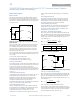
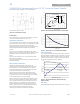
Trim Down – Decrease Output Voltage
By connecting an external resistor between the TRIM pin and
Vout+ pin (Radj-down), the output voltage set point decreases
(see figure 11). The following equation determines the external
resistor value to obtain an output voltage change from V
o,nom
to the desired V
o,adj
:
H
VV
GV
R
adjonomo
adjo
downadj
)(
)5.2(
,,
,
Note: Values for G and H are defined in Table 1.
Table 1. Trim Constants SHHD series
Vout+
TRIM
Vout-
R
adj-down
R
LOAD
Vin+
ON/OFF
Vin-
Figure 11. Circuit Configuration to Decrease Output Voltage.
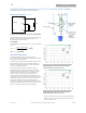
Trim Up – Increase Output Voltage
By connecting an external resistor between the TRIM pin and
Vout- pin (Radj-up), the output voltage set point increases (see
figure 12). The following equation determines the external
resistor value to obtain an output voltage change from V
o,nom
to the desired V
o,adj
:
H
KV
G
R
adjo
upadj
)5.2(
5.2
,
Note: Values for G, H and K are defined in Table 1.
The combination of the output voltage adjustment and the
output voltage initial tolerance must not exceed the allowable
trim range of 90% to 110% of the nominal output voltage as
measured between the Vout+ and Vout- pins.
Module G H K
SHHD003A0A 5110 2050 2.5