
Instruction Manual

GE
Data Sheet
SHHD003A0A Hammerhead
Series; DC-DC Converter Power Modules
18-75Vdc Input; 5.0Vdc, 3A, 15W Output
June 26, 2013 ©2012 General Electric Company. All rights reserved. Page 9
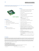
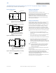
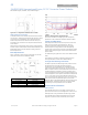
Figure 16. T
ref
Temperature Measurement Location.
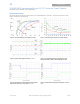
Heat Transfer via Convection
Increased airflow over the module enhances the heat transfer
via convection. Derating figures showing the maximum output
current that can be delivered by each module versus local
ambient temperature (T
A
) for natural convection and up to
3m/s (600 ft./min) are shown in the respective Characteristics
Curves section.
Please refer to the Application Note “Thermal Characterization
Process For Open-Frame Board-Mounted Power Modules” for a
detailed discussion of thermal aspects including maximum
device temperatures.
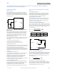
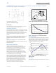
EMC Requirements
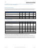
Figure 17 shows a maximum filter configuration to meet the
conducted emission limits of EN55022 Class B.
Ref Des Filter
C1 , C2, C3 2.2uF/100V
C4, C5 33nF Y cap
L1 4mH CM choke
L2 10uH inductor
Figure 17. Suggested Configuration for EN55022 Class B.
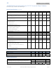
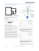
Figure 18. EMC signature using above filter.
For further information on designing for EMC compliance,
please refer to the FLTR100V10 data sheet (FDS01-043EPS).
Layout Considerations
The SHHD power module series are low profile in order to be
used in fine pitch system card architectures. As such,
component clearance between the bottom of the power
module and the mounting board is limited. Avoid placing
copper areas on the outer layer directly underneath the power
module. Also avoid placing via interconnects underneath the
power module.
For additional layout guide-lines, refer to the FLTR100V10 data
sheet.
The SHHD family of power modules is available for either
Through-Hole (TH) or Surface Mount (SMT) soldering.
Through-Hole Soldering Information
The RoHS-compliant (Z codes) through-hole products use the
SAC (Sn/Ag/Cu) Pb-free solder and RoHS-compliant
components. They are designed to be processed through
single or dual wave soldering machines. The pins have an
RoHS-compliant finish that is compatible with both Pb and Pb-
free wave soldering processes. A maximum preheat rate of
3C/s is suggested. The wave preheat process should be such
that the temperature of the power module board is kept below
210C. For Pb solder, the recommended pot temperature is
260C, while the Pb-free solder pot is 270C max. The Through
Hole module is also compatible with paste-in-hole reflow
soldering. Refer to the Reflow Soldering Information section for
process details. If additional information is needed, please
consult with your GE representative for more details.
Surface Mount Information
Pick and Place
The SHHD-SR series of DC-to-DC power converters use an
open-frame construction and are designed for surface mount
assembly within a fully automated manufacturing process.
The SHHD-SR series modules are designed to use the main
magnetic component surface to allow for pick and place.