
User Manual


14 MDS 1710A/C and MDS 2710A/C/D MDS 05-3447A01, Rev. F
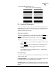
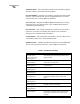
Table 4. DATA INTERFACE Connector Pinouts
Pin
Number
Input/
Output Pin Description
1--Protective Ground. Connects to ground (negative supply
potential) on the radio’s PC board and chassis.
2INTXD—Transmitted Data. Accepts TX data from the
connected device.
3 OUT RXD—Received Data. Outputs received data to the
connected device.
4INRTS—Request-to-Send Input. Keys the transmitter when
RTS is at logic high.
5 OUT CTS—Clear-to-Send Output. Goes “high” after the
programmed CTS delay time has elapsed (DCE) or keys
an attached radio when RF data arrives (CTS KEY).
6 OUT DSR—Data Set Ready. Provides a +6 Vdc DSR signal
through a 2.5 kΩ resistor.
7--Signal Ground. Connects to ground (negative supply
potential) at radio’s PC board.
8 OUT DCD—Data Carrier Detect. Goes “high” when the modem
detects a data carrier from the master station.
9INTransmit Audio Input. Connects to the audio output of an
external (AFSK) modem. The input impedance is 600 Ω.
Use Pin 7 for the modem’s return lead.
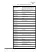
10 OUT RUS—Receiver Unsquelched Sensor. Not used in most
installations, but is available as a convenience. Provides
+8 Vdc through a 1 kΩ resistor whenever the receiver
squelch is open, and drops to less than 1 Vdc when the
squelch is closed.
11 OUT Receive Audio Output. Connects to the audio input of an
external (AFSK) modem. The output impedance is 600 Ω,
and the level is factory set to suit most installations. Use
Pin 7 for the modem’s return lead.
12 IN Radio Inhibit (Sleep). A ground on this pin places the
radio into the “sleep” mode. It turns off most circuits in the
radio, including transmit, receive, modem and diagnostic
functions. This allows for greatly reduced power
consumption, yet preserves the radio’s ability to be quickly
brought online.
13 -- Do not connect—Reserved for future use.
14 IN PTT—Push to Talk. This line is used to key the radio with
an active-high signal of +5 Vdc.
15 OUT Remote RTU Reset. Do not connect—Reserved for future
use.
16 IN PTT
—Push to Talk. This line is used to key the radio with
an active-low signal of 0 Vdc.
17 -- Do not connect—Reserved for future use.
18 IN/OUT Accessory Power. Unregulated Input/Output. Provides a
source of input power for low current accessories.
Excessive drain on this connection will trip self-resetting
fuse F1 on the transceiver PC board. The voltage at this
pin will match the input voltage to the transceiver.