
User's Manual


TRAIN CHIEF® II LRCS w/Lightweight OCU OWNER’S MANUAL
95-00-0-xxx Rev 000 1-1 Control Chief Corporation
1 INTRODUCTION / SAFETY
Introduction
This Owner’s Manual provides operating and troubleshooting information for the installer and
end user of the Train Chief® II Locomotive Remote Control System (LRCS) with a Lightweight
Operator Control Unit (OCU) Brake & Throttle variant for Industry (BTIND).
The Train Chief® II LRCS has been designed as a permanently installed (“fixed”) system,
directly interfaced to the appropriate locomotive electrical and pneumatic controls. The system
consists of the following main components: (1) - the Receiver / Controller Unit (RCU), (2) - the
wireless remote-control radio OCU, (3) - the installation kit.
Common Acronyms
CFR - Code of Federal Regulations RCL - Remote Control Locomotive
FRA - Federal Railroad Administration RCO - Remote Control Operator
LRCS - Locomotive Remote Control System RCU - Receiver / Controller Unit
OCU - Operator Control Unit RCT - Remote Control Transmitter
PTC - Positive Train Control RCR - Remote Control Receiver
PLC - Programmable Logic Controller
Receiver / Controller Unit
The RCU contains the main control electronics and pneumatic hardware of the remote control
system. This includes; the PLC controller (the Allen Bradley SLC 500™), the Control Chief
Communicator® module and Control Chief Watchdog module, analog and discrete interface
modules, pneumatic proportional control valves, air regulation, control relays, solenoid valves,
and pressure sensing devices.
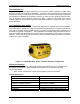
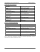
The RCU interface to the locomotive involves both
electrical and pneumatic connections. The
electrical interface is primarily accomplished
through DC relay contact closures, wiring into the
locomotive’s existing electrical control system. The
pneumatic interface typically involves direct air
service tie-ins using the dedicated pneumatic
control devices in the RCU. A dedicated DC/DC
converter and line conditioning module are
provided to interface the locomotive’s existing DC
supply to the RCU.
Figure 1-1 – The Receiver / Controller Unit