
User Manual

MDS 05-4218A01, Rev. 01 eNETL2W 20-Watt Power Amplifier Page 1 of 1
INTRODUCTION
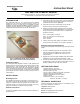
The eNETL2W (Figure 1) is a 20-watt RF power amplifier
designed for use in the 217–222 MHz frequency range. It is
intended to serve as a 100% duty cycle amplifier for MDS
entraNET 220 radio modules (ROR220) operating in point-to-
multipoint repeater applications. The amplifier is designed to
comply with FCC Part 90 and FCC Part 15 requirements.
Figure 1. MDS eNETL2W RF Power Amplifier
(Top cover removed to show internal layout)
Product Description
The eNETL2W power amplifier consists of a RF amplifier and
PCB mounted to a heat sink, with a DC Power interface, power
control interface, and input/output RF connections on the
sidewalls of the chassis. DC power is supplied to the amplifier
from a regulated and filtered DC source capable of supplying
10-16 Vdc at a maximum current of 5 Amperes. The DC power
source should be current limited or have a protective fuse or
circuit breaker.
INSTALLATION
Mounting the Unit
The amplifier is designed for mounting in a standard 19 -inch
rack cabinet using the 3U panel provided. Four screws (not pro-
vided) are required to attach the panel to the rack sides. This
panel also serves as a heat sink for the PA module, and is nor-
mally mounted with the cooling fins facing outward.
External Connections
To place the amplifier module in service, make the following ca-
ble connections:
1. Using low loss 50-ohm coaxial cable, connect the RF Input
connector (J103) to the RF output connector of the MDS
entraNET 220 radio module (ROR220).
2. Using low loss 50-ohm coaxial cable, connect the RF
Output connector (J102) to the station duplexer.
3. Connect the Power Control interface (J101) to the MDS
entraNET 220 radio module (ROR220) in accordance with
the pin connections listed below. J101 is an 8-pin Molex
polarized connector.
Pin 1—3 Vdc enable TX, low=off
Pin 2—0.7 Vdc (varies to set RF power)
Pin 3—Not used
Pin 4—Ground
4. Connect 10-16 Vdc power supply to the Power connector
(J100). The left pin is positive (+); the right is negative(–).
RF Power Output Check/Adjustment
To check/set the amplifier’s RF power output level, proceed as
follows:
1. Connect a wattmeter (rated for use at 220 MHz, and at
least 20 watts) to the amplifier’s RF output connector
(J102). Terminate the wattmeter into a 50-ohm, non-
inductive load.
2. Apply RF drive from the MDS entraNET 220 radio module
(ROR220) and note the RF power indication at J102.
3. If necessary, adjust R115 (see Figure 1) with an insulated
flat blade tool to achieve the desired output level. Access to
R115 is available through a top cover vent slot.
UNIT SPECIFICATIONS
Operating Voltage: 10-16 Vdc
Maximum Current Draw: 5 Amperes
RF Drive Power: 100 mW
RF Out: +40 to +43 dBm (10-20 watts), adjustable
Operating Frequency: 217-220 MHz
Mounting: standard 19-inch rack cabinet
Weight: 5.15 lbs.
Dimensions: 5.25” H x 19” W x 2.88” D
(13.34 H x 48.26 W x 7.31 D cm)
TECHNICAL ASSISTANCE
Technical assistance for MDS products is available by using
one of these methods to contact us:
Telephone:
585.241.5510
FAX:
585.242.8369
E-mail:
techsupport@microwavedata.com
Web:
www.microwavedata.com
Instruction Sheet
MDS eNETL2W 20-Watt RF Amplifier
Microwave Data Systems Inc., 175 Science Parkway, Rochester, NY 14620 USA
Tel. 585.242-9600 FAX 585.242-9620 www.microwavedata.com