
User's Manual


GPA-1 manual
2.5 R112PowerControlAdjustment
R112isusedtoadjusttheRFpoweroutputoftheamplifierininternalandmode.Turnthepotentiometer
clockwiseforhigherpowerandcounterclockwiseforlowerpower.
3 Installation
3.1 MountingtheUnit
TheGPA‐1isdesignedformountinginastandard19–inchrackcabinetusingthe3Upanelprovided.Four
screws(notprovided)arerequiredtoattachthepaneltotheracksides.Thispanelalsoservesasaheat
sinkforthePAmodule,andisnormallymountedwiththecooling
finsfacingoutward.
3.2 ConnectingtheUnit
Placetheamplifiermoduleinservicebymakingthefollowingcableconnections.
1. Usinglowloss50‐ohmcoaxialcable,connecttheRFInputconnector(J103)totheRFoutput
connectoroftheMDSSD1radio.
2. Usinglowloss50‐ohmcoaxialcable,connecttheRFOutputconnector(J102)
tothestation
duplexerorantenna.
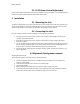
3. ForusewithSD1transceiverfollowthesesub‐steps,PWRsetbetween23‐27dBm(inputpower).
Donotuseabove27dBmforGPA‐1input.MoveJumperJ104totheInternalKeyingpositionas
showninFigure1AccesstoJ104isavailable
throughatopcoverventslot.
4. Connect10‐16VdcpowersupplytothePowerconnector(J100).Theleftpinispositive(+);the
rightisnegative(–).
3.3Alignment(Settingpoweroutput)
AdjustingRFPowerOutput
Tocheck/settheamplifier’sRFpoweroutput,proceedasfollows.
1. Connectawattmeter(ratedforuseat150MHz,andatleast40watts)totheamplifier’sRF
outputconnector(J102).
2. Terminatethewattmeterintoa50‐ohm,non‐inductiveload.
3. SetSD1
PWR=23dBm
4. ApplyRFdrivefrom150MHzradioandnotetheRFpowerindicationatJ102.
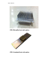
5. Ifnecessary,adjustR112(seeFigure2)withaninsulatedflatbladetooltoachievethedesired
outputlevel.Accesstothiscontrolisavailablethroughatopcoverventslot.