
Installation Instructions

MDSLN400Integrator’sGuide 05‐6738A01,revision8
[2]
2.0INSTALLATION
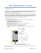
The transceiver is designed for installation in existing electronic equipment. The I/O and 5.25v power connections are
made through the Mini PCI-Express card edge. The 10-60v power is provided through a separate 3-pin connector on
the bottom of the module. The transceiver mounts to the host heatsink assembly using two #4 screws inside the RF
can area. The required heatsink contact area on the bottom surface of the PCB has the solder mask removed for
proper heat transfer.
Only one cable connection is required to the radio for the J700 Antenna connector. The module has three optionally
populated status LEDs (CR100, CR101, and CR1000) that indicate operating mode details. These LEDs provide
important information that is useful during startup and optimization of the radio link.
Antennas used with the radio can be either a Yagi directional type (often used at remote sites) or an omni-directional
type used for short range applications or at Master stations. Contact your sales representative for information on
available antennas.
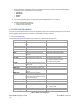
Follow these steps to install the transceiver module:
1. Power down the Host assembly the module is being installed in to.
2. Mate the MiniPCIe card edge of the module into the socket on the Host assembly.
3. Secure the module to the heatsink surface using two #4 screws through the mounting holes in the corners of
the RF can area on the radio’s PC board.
4. Install the RF shield over the transceiver section.
5. Select and install an appropriate antenna and feedline for your system coverage requirements.
6. Connect the antenna coaxial lead to J700 on the module. It accepts a Type-TNC male coaxial connector.
7. External RX filtering can be installed if needed using UMC connectors J701 (RX-OUT) and J702 (RX-IN).
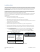
8. Host Power Supply Requirements:
a. Input power applied on the 52-pin connector (J1100) must be a regulated 5.25 Vdc (-/+0.05 V).
b. Input power applied on 3-pin connector (J900) must not exceed the range 10.0-60.0Vdc
i. Nominal Input power on J900 is in the range 12-52Vdc - FCC CFR 47 2.1055(d)(1)
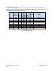
See Table 1 for power supply interface connections.
52-Pin GE MDS NIC Card Edge
Pin Description
1, 6, 7, 10, 11, 13, 12, 14,
16, 19, 20, 23, 25, 28, 30,
31, 32, 33, 36, 38, 42, 44,
45, 46, 47, 48, 49, 51
GPIO
(Includes Ethernet &
Serial)
*Consult Factory
Documentation for
specific details
2, 24, 39, 41, 52 +5.25
V
3, 5, 8, 17, 22 NC
4, 9, 15, 18, 21, 26, 27,
29, 34, 35, 37, 40, 43, 50
GND
Table 1. LN400 Power Supply Connections
3-Pin GE MDS (J900) connecto
r
Pin Description
1GND
2, 3 +10.0-60.0V