
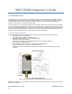
Installation Instructions

MDSLN400Integrator’sGuide 05‐6738A01,revision8
[3]
9. Set the radio’s basic configuration with a PC terminal through the Host system. The four essential settings
for all transceivers are (See Section 3 for commands):
Frequency
Bandwidth
Modem
Power
10. In a normally operating system, you will see the CR101 POWER LED turn on at start-up.
11. Optimize the installation by checking:
Antenna aiming and RSSI check
Optimal modem rate setting
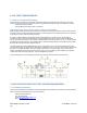
3.0RADIOPROGRAMMING
There are no manual adjustments on the radio. All programming and control is performed through a PC connected to
the Host platform that interfaces with the radio’s J1100 MiniPCIe card edge connector.
3.1UserCommands
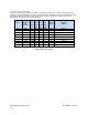
The following tables provide descriptions of the various user commands for the transceiver.
Command Description Notes
ABOUT DisplaysNICversionbuildtimeand
date.
HELP Displaysallavailablecommands.
RESETSoftwarereset.
SER DisplaytheNICserialnumber.
MODEM Display/setNICmodemselection. [4QAM,16QAM,64QAM,9600,19200
]
BAUD Display/setNICsymbolbaudrate
selection.
[4800,9600,10000,16000,20000
]
TESTADDR Read/writetestaddress. [0‐7]Addressusedfortests(e.g.PER
)
TESTPER StartsaPacketErrorRateTest. [‐a]Destinationtestaddress
[‐n]Numberofpacketstosend
[‐l]Lengthofeachpacket
UPTIME Displaytheamountoftimesincelast
powercycle.
MDMKEY Transmitsun‐modulatedCW
MDMKEYR Transmitsmodulatedrandomdata
MDMKEYLO TransmitspassthroughofLOthrough
TXchain
MDMDKEY Disablesactivetransmission
MDMPRBURST Transmitsamodulatedrandomdata
burstof511bytes,usefulfortraining
thereceiverequalizer
MDMRSSI! InstantaneousRSSIreading dB
TX[val] Read/writeTXfrequency [val]‐ frequencyinMHz
RX[val] Read/writeRXfrequency [val]‐ frequencyinMHz
TRSWRXD[val] RouteRXSignal [TR]‐ RXfromJ70
0
[R]‐RXfromJ702
TCXO[arg1] ChangeTCXOtuningvoltage [arg1]‐ Tuningvoltagein
V
TCXOCAL[arg1] CalibrateTCXOtuningvoltage [arg1]‐ Tuningvoltagein
V
Table 2. LN400 User Commands