
User's Manual
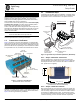
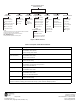
Table Of Contents

2 MDS Mercury Series Quick Start 05-6301A01, Rev. 01
Install GPS Antenna (if required)
Install the GPS antenna in accordance with the manufacturer’s
instructions. Connect it to the GPS Port on the unit’s front panel.
2.1.3 Step 3—Measure & Connect DC Power
The DC input to the transceiver must be within 10–60 Vdc and
capable of continuously providing at least 150 watts. A power con-
nector with screw-terminals is provided with each unit. Strip the
wire leads to 6 mm (1/4 inch). Be sure to observe proper polarity
with the positive lead (+) on the left, and the negative on the right.
The unit is designed for use in negative ground systems only.
The power supply should be equipped with
overload protection (NEC Class 2), to protect
against a short circuit between its output ter-
minals and the radio’s power connector.
NOTE: It takes about 30 seconds for the unit to fully power up,
and a few minutes to associate with another unit, espe-
cially if GPS is required for time synchronization.
2.1.4 Step 4—Review the Transceiver’s
Configuration
One key setting must be known before beginning configuration:
• IP Address—Must be a unique address to allow for IP
access through the LAN port or over-the-air. Check with
your System Administrator for this information. (Default
address is 192.168.1.1)
Other parameters commonly needing review or adjustment are
listed below, followed by Log-in and Configuration procedures.
• RF Output Power Level (BS Only)—Check and adjust as
necessary for compliance with regulatory limits. (Default
power is +30 dBm for 1800 model, +23 dBm for 3650
model.) Note that Subscriber Units auto-adjust power output
based on target receive signal level (set at the BS).
• Password—Used for remote access and Menu System.
• Frequency—Operating frequency in MHz.
• TDD Sync Mode (BS only)—Selections are: Free Run and
GPS Required.
Free Run allows rapid configuration and initial testing.
GPS Required synchronizes the BS’s transmissions to the
GPS timing. GPS Required is only needed to synchronize
multiple Base Stations.
NOTE: The default password and username is admin.
A unique IP address and subnet are required to access the Menu
System, either through the LAN port, or remotely over-the-air.
Log-in and Configuration Procedure
The following is an overview of the local log-in and configuration
procedure using the COM1 serial port.
a. Connect a computer’s serial port to the unit’s COM1 Port.
b. Launch a terminal communication program, such as
HyperTerminal, on the computer. Configure it to: 115,200
bps/8N1/no handshaking/VT100.
c. Press ENTER. A login prompt is displayed that requires a
username and password.
d. Enter the username and password.
e. Review other settings and make changes as necessary,
such as the unit password, IP address, and security.
f. Under the Radio Configuration Menu at the Base Station,
set/verify the following:
Transmit Power—Settable from: -30 dBm to +30 dBm
(BS); 0 dBm to +30 dBm (SU); +23 dBm for 3650 models.
Receive Power—Target receive signal of the BS which
SUs will seek to adjust to, based on distance.
g. Under the Frequency Control Menu of the Radio Con-
figuration Menu, set/verify as required. Ensure that the
SU’s radio parameters are consistent with the BS's Fre-
quency Parameter.
Repeat above steps for each radio in the network. An overview
chart of the entire Menu System is shown in Figure 4 on Page 4.
NOTE: Using Configuration Scripts under the Mainte-
nance/Tools menu can aid in configuring multiple units.
2.1.5 Step 5—Connect the Data Equipment
Connect data equipment to the unit’s LAN port (10/100 BaseT), or
the serial port, depending on the type of equipment used.
Use a straight-through Ethernet cable to connect the
LAN port to a
hub or switch; use a crossover cable to connect it directly to an
Ethernet device (PC, PLC, RTU).
2.1.6 Step 6—Check for Normal Operation
This step verifies the proper operation of wireless communications
between a BS and its associated SUs.
At All Units...
Observe the transceiver’s LED panel for the proper indications
(see Table 1). In a normally operating system, the radio will typi-
cally become associated in about two minutes from start-up.
At the Base Station...
a. If the BS is the first unit you are installing, send a PING
command to it through the LAN port. This verifies basic
LAN connectivity.
b. If you have already installed an SU, try sending a PING to
that unit through the Menu System PING utility or a
device connected to the unit on the same subnet.
At Subscriber Units...
a. Look for the LINK LED to turn on and stay on. This indi-
cates the unit has successfully associated with the net-
work’s Base Station. (The may take up to 30 seconds.)
b. View the Starting Information screen for the Device Sta-
tus and Connection Status). It will show one of these:
Initializing—This is the first phase after boot-up.
Scanning—The unit is looking for a Base Station beacon signal.
Ranging—Unit is adjusting power, timing, & frequency with a BS.
Authenticating—(When Device Authentication is used.) The SU
is authenticating to the network to obtain clearance.
Associated —The unit has successfully synchronized and associ-
ated with a Base Station. This is the normal state of the radio.
Alarmed—The unit has detected one or more uncleared alarms.
c. When the network is operating properly based on obser-
vation of the unit’s LEDs, connect a computer to the trans-
ceiver’s data port that will be used by the local terminal
equipment. Send the PING command to verify communi-
cations integrity with the Base Station.
d. After the PING is successful, connect the terminal equip-
ment to the radio’s data port and verify normal operation.
If above checks are OK, you are finished with the installation at this
site.
CAUTION
POSSIBLE
EQUIPMENT
DAMAGE