
User's Manual
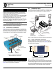
Table Of Contents

05-6301A01, Rev. 01 MDS Mercury Series Quick Start Guide 3
2.2 ANTENNA AIMING
Directional antennas usually require some fine-tuning of their
bearing to optimize the received signal strength. The SU has a
built-in received signal strength indicator (RSSI) that can be used
to optimize the received signal level. It is available under the Per-
formance Information menu.
In general, signal levels stronger than –80 dBm will provide reliable
communication in the network. RSSI measurements and Wireless
Packet Statistics are based on multiple samples over a period of
several seconds. The average of these measurements is dis-
played by the RSSI screen. Follow the steps below to aim the
antenna for best received signal level.
2.2.1 Procedure
1. Verify the SU is associated with a Base Station unit by
observing the LINK LED. It should be on or blinking.
2. a) View and record the Wireless Packets Dropped and
Received Error rates (Main Menu>Performance Informa-
tion>Packet Statistics). This information will be used later.
b) Read the RSSI level at the Subscriber Unit (Main
Menu>Performance Information>Internal Radio Status).
3. Optimize RSSI by slowly adjusting the direction of the
antenna. Watch the RSSI indication for several seconds after
making each adjustment so that the RSSI accurately reflects
any change in the link signal strength. The less negative the
number, the stronger the signal.
4. View the Wireless Packets Dropped and Received Error
rates at the point of maximum RSSI level (Main Menu>Per-
formance Information>Packet Statistics). They should be
the same or lower than previously noted.
If the RSSI peak results in an increase in the Packets
Dropped and Received Error numbers, the antenna may be
aimed at an undesired signal. Try a different antenna heading.
2.3 TROUBLESHOOTING
It is best to begin troubleshooting at the BS, as the rest of the
system depends on it for network synchronization and configura-
tion. If the BS has problems, the operation of the entire network will
be affected.
All radios in the network must meet these basic requirements:
• Adequate and stable primary power
• An efficient and properly aligned antenna system
• Secure connections (RF, data & power)
• Proper programming of the unit’s operating parameters,
especially Frequency Selection and IP Address
• The correct interface between the radio and the connected
data equipment (proper cable wiring, data format and timing)
A chart of LED functions is provided on Page 4 of these instruc-
tions. Refer to the Technical Manual for suggestions on resolving
common system difficulties using the radio’s LEDs and Menu
system as a guide.
If problems cannot be resolved using the guidance provided here,
review the GE MDS website’s technical support area for recent
software/firmware updates, general troubleshooting help, and ser-
vice information. Additional help is also available from our Tech-
nical Services Department.
2.3.1 Resetting to Factory Defaults
In trouble cases where several menu parameters have been
changed and there is no track of changes, it may help to return the
unit to a known, factory default state. Configuration can then be
attempted again. Use this function with care, as all user-custom-
ized settings will be cleared.
To reset to factory defaults, select Maintenance/Tools>Reset to
Factory Defaults.
2.4 APPROVAL INFORMATION
2.4.1 FCC Part 15 Notice
The transceiver series complies with Part 15 of the FCC Rules.
Operation is subject to the following two conditions: (1) this device
may not cause harmful interference, and (2) this device must
accept any interference received, including interference that may
cause undesired operation. Any unauthorized modification or
changes to this device without the express approval of GE MDS
may void the user’s authority to operate this device. Furthermore,
the Mercury Series is intended to be used only when installed in
accordance with the instructions outlined in this guide. Failure to
comply with these instructions may void the user’s authority to
operate this device.
Part 15 rules also require that the Effective Isotropic Radiated
Power (EIRP) from a Mercury Series 1800 MHz installation not
exceed 36 dBm. For the Mercury 3650, EIRP must not exceed
1-watt per MHz.
NOTE: This equipment has been tested and found to comply with
the limits for a Class A digital device, pursuant to part 15 of the
FCC Rules. These limits are designed to provide reasonable pro-
tection against harmful interference when the equipment is oper-
ated in a commercial environment. This equipment generates,
uses, and can radiate radio frequency energy and, if not installed
and used in accordance with the instruction manual, may cause
harmful interference to radio communications. Operation of this
equipment in a residential area is likely to cause harmful interfer-
ence in which case the user will be required to correct the interfer-
ence at his own expense.
2.4.2 RF Exposure Notices
1800 MHz Models
Professional installation required. The radio equipment
described in this guide emits radio frequency energy. Although the
power level is low, the concentrated energy from a directional
antenna may pose a health hazard. Do not allow people to come
closer than 23 cm (9 inches) to the antenna when the transmitter
is operating in indoor or outdoor environments. More information
on RF exposure is on the Internet at
www.fcc.gov/oet/info/documents/bulletins.
3650 MHz Models
Professional installation required. The transceiver described
here emits radio frequency energy. Although the power level is low,
the concentrated energy from a directional antenna may pose a
health hazard. Do not allow people to come closer than 25 cm (9.8
inches) to the antenna when the transmitter is operating. This cal-
culation is based on an 18 dBi panel antenna. Additional informa-
tion on RF exposure is available on the Internet at
www.fcc.gov/oet/info/documents/bulletins.