
User's Manual
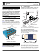
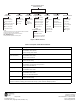
Table Of Contents

GE MDS, LLC
175 Science Parkway
Rochester, NY 14620
MDS Mercury Series Setup Guide General Business: +1 585 242-9600
05-6301A01, Rev. 01 FAX: +1 585 242-9620
November 2010 (Copyright 2010, GE MDS, LLC) Web: www.gemds.com
Invisible place holder
Figure 4. Menu Overview
Table 1: Description of LED Status Indicators
LED Name Description
PWR • ON—Power applied, no problems detected.
• FLASHING—Alarm present
• OFF—Primary power absent
LAN
(See Note below)
• ON—LAN detected.
• FLASHING—Data TX/RX
• OFF—LAN not detected
COM1 • FLASHING—Data TX/RX activity
• OFF—No data activity
GPS • ON—Has GPS satellite fix
• FLASHING—Synchronizing timing reference
• OFF—No GPS satellite fix
LINK (BS) • ON—Operational state
• FLASHING—Data TX/RX
LINK (Subscriber) • ON—Associated to BS
• FLASHING—Data TX/RX
• OFF—Not Associated with BS
USB • ON—USB activity on either port
• OFF—No USB activity
NOTE: The unit’s LAN port also has two embedded LEDs to indicate signal activity as follows: A steady green indicates that a link
has been achieved; a flashing green indicates data activity; a yellow indicates 100 Mbps operation.
Ntwk. Intfc. Config
Ethernet Port Config
Bridge Configuration
SNMP Agent Config. (BS)
AP Location Info (SU)
Network
Configuration
Radio
Configuration
Device
Information
Maintenance/Tools
Security
Configuration
Reprogramming
Config. Scripts
Ping Utility
Auth. Codes
Reset to Defaults
Radio Test
F/W Versions
F/W Upgrade
MAIN MENU
Transmit Power
Receive Pwr. (BS)
Freq. Control
Adv. Config.
Performance
Information
Serial Number
Uptime
Date
Date Format
Time
Model
Device Names
Console Bd. Rt.
UTC Time Offset
Device Security
Wireless Security
Event Log
Packet Statistics
GPS Status
Wireless Ntwk Stat.
WiMAX Radio Stat.
PerformanceT rend
Manage Certif.
RADIUS
Configuration
Starting Information Screen
(Read-Only Status)
Redundancy
Configuration (BS)
Redundancy Config.
Ntwk Event Triggers
Radio Event Triggers
Hdwr Event Triggers
Red. Config. Options
Force Switchover
SNTP Server Config.
802.11 Configuration
GPS
Configuration (SU)
Stream GPS to Console
Send GPS via UDP
GPS UDP Server IP Address
GPS UDP Server UDP Port
Spacebar is used to make some menu selections
BS = Base Station Only
SU = Subscriber Unit Only
NOTES
Chart shows top-level view only. See Reference Manual for details.
Not all menu items are-user configurable
Some parameters dependent on radio options