Wireless IP/Ethernet Transceiver Covering AP and Remote Units DRAFT MDS 05-4446A01, Rev.
TABLE OF CONTENTS 1 PRODUCT OVERVIEW AND APPLICATIONS............ 1 1.1 ABOUT THIS MANUAL......................................................................................................... 3 1.1.1 Start-Up Guide ...........................................................................................................................3 1.1.2 Online Access to Manuals ..........................................................................................................3 1.1.
2.4 STEP 3—CONNECT PC TO THE TRANSCEIVER............................................................ 23 2.5 STEP 4—REVIEW TRANSCEIVER CONFIGURATION .................................................... 23 2.5.1 Getting Started .........................................................................................................................23 2.5.2 Procedure .................................................................................................................................23 2.5.
3.7.3 IEEE 802.1x Device Authentication ..........................................................................................89 3.7.4 Manage Certificates .................................................................................................................91 3.8 REDUNDANCY CONFIGURATION (AP ONLY) ................................................................. 93 3.9 GPS CONFIGURATION (REMOTE ONLY) ........................................................................ 98 3.
- 5.1.7 A Word About Radio Interference ...........................................................................................156 5.2 dBm-WATTS-VOLTS CONVERSION CHART .................................................................. 158 6 TECHNICAL REFERENCE..................................... 159 6.1 DATA INTERFACE CONNECTORS ................................................................................. 161 6.1.1 LAN Port ........................................................................
The majority of GE MDS radios deployed since 1985 are still installed and performing within our customers’ wireless networks. That's because we design and manufacture our products in-house, according to ISO 9001 which allows us to control and meet stringent global quality standards.
CSA Conditions of Approval: The transceiver is not acceptable as a stand-alone unit for use in the hazardous locations described above. It must either be mounted within another piece of equipment which is certified for hazardous locations, or installed within guidelines, or conditions of approval, as set forth by the approving agencies. These conditions of approval are as follows: The transceiver must be mounted within a separate enclosure which is suitable for the intended application.
1 PRODUCT OVERVIEW AND APPLICATIONS 1 Chapter Counter Reset Paragraph Contents 1.1 ABOUT THIS MANUAL ............................................................... 3 1.1.1 Start-Up Guide .............................................................................. 3 1.1.2 Online Access to Manuals ............................................................. 3 1.1.3 Conventions Used in This Manual ................................................ 3 1.2 PRODUCT DESCRIPTION ..............................
2 Mercury Reference Manual 05-4446A01, Rev.
1.1 ABOUT THIS MANUAL This Reference Manual is one of two publications provided for users of the Mercury SeriesTM transceiver system. It contains detailed product information, an overview of common applications, a screen-by-screen review of the menu system, technical specifications, suggested settings for various scenarios, and detailed troubleshooting information. This manual should be available to all personnel responsible for network design, setup, commissioning and troubleshooting. 1.1.
Menu Strings To help show the path to a menu selection, navigation strings are used in several places in this manual. For example, suppose you want to view or set the Network Name assigned to your system. This item is located in the Network Configuration Menu, so the navigation string in the text would appear as shown: Main Menu>>Network Configuration>>Network Name By following this order of menus, you can quickly reach the desired menu. 1.
This one enclosure contains all necessary components for radio operation and data communications. Simple Installation Mercury Transceivers are designed for rapid and trouble-free installation. For basic services, you simply connect the antennas (900 MHz and GPS, as required), connect your data equipment, apply primary power, and set some operating parameters. No license is required for operation in the USA, Canada, and many other countries.
Flexible Management You can locally or remotely configure, commission, troubleshoot, and maintain the transceiver. Four different modes of access are available: local RS-232 console terminal, local or remote IP access (via Telnet or SSH), web browser (HTTP, HTTPS), and SNMP (v1/v2/v3). The text-based interfaces (RS-232 console, Telnet, and SSH) are implemented in the form of easy-to-follow menus, and the terminal server provides a wizard to help you configure the units correctly.
gasket seal in the center of the radio case. APs have a black gasket, while Remote units have a yellow gasket. In addition to gasket color, a label on the top of each radio identifies it as an AP or Remote unit. If the label shows an –A suffix, it is an AP. If it shows a –R suffix, it is a Remote. 1.2.2 GE MDS P23 Protected Network (Redundant) Configuration For mission-critical applications, a Protected Network Station is also offered.
1.3.1 Mobile/Fixed Data System Mercury transceivers support high-speed data communications in a mobile environment. In this application, Remote radios “roam” between different Access Points, providing seamless transitions and continuous coverage throughout a municipal area. Figure 1-3 shows an example of an integrated system employing both mobile and fixed Mercury transceivers.
InvisibleRemote place holder LAN Remote Remote LAN LAN WAN/LAN Remote LAN Access Point Figure 1-4. Typical Wireless LAN 1.3.3 Point-to-Point LAN Extension A point-to-point configuration (Figure 1-5) is a simple arrangement consisting of an Access Point and a Remote unit. This provides a communications link for transferring data between two locations. Invisible place holder Access Point Remote LAN/WAN LAN Figure 1-5. Typical Point-to-Point Link 1.3.
Invisible place holder Serial Device Serial Conn. MDS 4710 Remote NETWORK Remote Serial ROUTER Serial Device MDS 4790 Master MDS 4710 Remote ROUTER Access Point HUB Serial Device Serial Conn. MDS 9710 Remote Remote Serial Serial Device MDS 9790 Master MDS 9710 Remote NMS Control Point SCADA Host Modbus/IP Serial Device MDS 9810 Remote Serial Conn. Remote Serial MDS 9810 Master Serial Device MDS 9810 Remote Figure 1-6. Backhaul Network 1.3.
By using a single radio, the cost of deployment is cut in half. Beyond requiring only one radio instead of two, the biggest cost reduction comes from using half of the required infrastructure at the remote site: one antenna, one feedline, one lightning protector and ancillary hardware. Other cost reductions come from the system as a whole, such as reduced management requirements.
1.3.7 Upgrading Older Wireless Network with Serial Interfaces Millions of wireless data products have been installed in the last two decades for licensed and license-free operation, many of them manufactured by GE MDS. There are several ways that these systems can benefit from incorporating Mercury equipment. The chief advantages are interface flexibility (serial and Ethernet in one unit), and higher data throughput.
tions. In this case, using high-gain Yagi antennas at each location provides more reliable communications than their counterparts— omnidirectional antennas. Invisible place holder Remote REPEATER T OIN LAN O-P T-T IN PO Access Point K LIN Access Point Ethernet Crossover Cable Remote LAN Remote Remote LAN/WAN LAN Figure 1-9. Typical LAN with a Repeater Link Overview Two transceivers may be connected “back-to-back” through the LAN ports to form a repeater station.
work names, see “STEP 3—CONNECT PC TO THE TRANSCEIVER” on Page 23. TDD Sync Mode To avoid interference between the two APs that form a repeater station, they should be synchronized so that they will transmit at the same time and receive at the same time. This eliminates the possibility of one AP transmitting while another is trying to receive. This can be accomplished by setting the TDD Sync Mode parameter in the menu to GPS Required. See Frequency Control Menu on Page 60 for details.
protected configuration for the Access Point to greatly reduce the possibility of this occurrence. Two or more Access Points can be configured identically, each with its own independent antenna. In this scenario, Remotes will associate with one of the available Access Points. In case of a failure of that AP, the Remotes will quickly associate with another Access Point, re-establishing connectivity to the end devices.
structure. If that does not work, consult with your factory representative about other techniques for controlling radio frequency interference between the radios. (See “A Word About Radio Interference” on Page 156 for more details.) 1.5 GE MDS CYBER SECURITY SUITE Today, the operation and management of an enterprise is increasingly dependent on electronic information flow. An accompanying concern becomes the cyber security of the communication infrastructure and the security of the data itself.
Table 1-2. Security Risk Management Security Vulnerability GE MDS Cyber Security Solution Unprotected access to configuration via SNMPv1 •Implement SNMPv3 secure Intrusion detection • Provides early warning via SNMP operation through critical event reports (unauthorized, logging attempts, etc.
Table 1-3. Accessories (Continued) 18 Accessory Description GE MDS Part No. 2-Pin Power Plug Mates with power connector on transceiver. Screw terminals provided for wires, threaded locking screws to prevent accidental disconnect. 73-1194A39 Ethernet RJ-45 Straight-thru Cable (CAT5) Cable assembly used to connect an Ethernet device to the transceiver. Both ends of the cable are wired identically. (Cable length ≈ 3 ft.
2 TABLETOP EVALUATION AND TEST SETUP 2 Chapter Counter Reset Paragraph Contents 2.1 OVERVIEW ............................................................................... 21 2.2 STEP 1—CONNECT THE ANTENNA PORTS ......................... 21 2.3 STEP 2—CONNECT THE PRIMARY POWER......................... 22 2.4 STEP 3—CONNECT PC TO THE TRANSCEIVER .................. 23 2.5 STEP 4—REVIEW TRANSCEIVER CONFIGURATION ........... 23 2.5.1 Getting Started .........................................................
20 Mercury Reference Manual 05-4446A01, Rev.
2.1 OVERVIEW GE MDS recommends that you set up a “tabletop network” to verify the basic operation of the transceivers. This allows experimenting with network designs, configurations, or network equipment in a convenient location. This test can be performed with any number of radios. When you are satisfied that the network is functioning properly in a benchtop setting, perform the field installation.
NOTE: Use attenuation between all units in the test setup. The amount of attenuation required depends on the number of units tested and the desired signal strength (RSSI) at each transceiver during the test. In no case should a signal greater than –50 dBm be applied to any transceiver in the test setup. GE MDS recommends an RF power output level of +20 dBm from the AP. Remote power is not setable. (See “Radio Configuration Menu” on Page 58.) 2.
2.4 STEP 3—CONNECT PC TO THE TRANSCEIVER Connect a PC’s Ethernet port to the LAN port using an Ethernet crossover cable. The LAN LED should light. Alternatively, you can use a serial cable to connect to the COM1 port (Figure 2-3 on Page 25). 2.5 STEP 4—REVIEW TRANSCEIVER CONFIGURATION 2.5.1 Getting Started Start by logging into the Access Point radio. This is done first because the Remotes are dependent on the AP’s beacon signal to achieve an “associated” state.
Table 2-1. Basic Configuration Defaults Item Menu Location Default Values/Range Network Name Main Menu>> Radio Configuration>> Network Name MDS-Mercury • 1–15 alphanumeric characters IP Address Main Menu>> Network Configuration>> IP Address 192.168.1.1 Contact your network administrator RF Output Power Main Menu>> Radio Configuration>> Transmit Power +30 dBm (1.0 Watt) AP: -30 to +30 dBm RM: 0 to +30 dBm (Max. 1.
Invisible place holder LAN PORT LED INDICATOR PANEL COM1 SERIAL PORT DC POWER INPUT (10—30 VDC, 2.5A) RX2 ANTENNA PORT GPS ANTENNA TX/RX1 CONNECTION ANTENNA PORT Figure 2-3. Transceiver Interface Connectors • LED INDICATOR PANEL—Displays the basic operating status of the transceiver. Section 2.7 on page 26 contains detailed information. • COM1 SERIAL PORT— DB-9 connector used for management of the transceiver using a connected PC. MS INTRODUCTION on Page 31 provides complete connection details.
2.7 STEP 6—CHECK FOR NORMAL OPERATION Once the data equipment is connected, you can check the transceiver for normal operation. Observe the LEDs on the top cover for the proper indications.
Table 2-2. Transceiver LED Functions (Continued) LED Label Activity Indication GPS ON Internal GPS receiver is synchronized with the satellite network. Blinking AP modem is synchronizing with the GPS timing. OFF Internal GPS receiver is not synchronized with the satellite network. LINK ON Default state (Access Point) OFF Not transmitting. Usually occurs while waiting for GPS sync.
28 Mercury Reference Manual 05-4446A01, Rev.
3 EMBEDDED MANAGEMENT SYSTEM 3 Chapter Counter Reset Paragraph Contents 3.1 MS INTRODUCTION................................................................. 31 3.1.1 Differences in the User Interfaces ............................................... 31 3.2 ACCESSING THE MENU SYSTEM .......................................... 33 3.2.1 Methods of Control ...................................................................... 34 3.2.2 PC Connection and Log In Procedures ......................................
3.9 GPS CONFIGURATION (REMOTE ONLY)............................... 98 3.10 DEVICE INFORMATION MENU............................................ 100 3.11 PERFORMANCE INFORMATION MENU ............................. 101 3.12 MAINTENANCE/TOOLS MENU.............................................113 3.12.1 Auto Firmware Upgrade Menu (AP Only) ...............................124 3.13 PERFORMANCE OPTIMIZATION ........................................ 127 3.13.1 Proper Operation—What to Look For .........................
3.1 MS INTRODUCTION The transceiver’s embedded management system is accessible through the COM1 (serial) port, the LAN (Ethernet) port, and using over-the-air Ethernet. Telnet, SSH, HTTP/HTTPS, and SNMP are the Ethernet-based interfaces. Essentially, the same capabilities are available through any of these paths. For support of SNMP software, a set of MIB files is available for download from the GE MDS Web site at www.GEmds.com.
Figure 3-1. Embedded Management System—Top-Level Flowchart 32 Mercury Reference Manual 05-4446A01, Rev. C Radio Test Performance Trend Date Format Force Switchover Adv. Config. AP Location Info (RM) NOTES • Chart shows top-level view only. See Reference Manual for details.
Figure 3-2. View of MS with a text-based program— (Console Terminal shown—Telnet has similar appearance) Invisible place holder Figure 3-3. View of the MS with a Browser (Selections at left provide links to the various menus) 3.2 ACCESSING THE MENU SYSTEM The radio has no external controls or adjustments. All configuration, diagnostics, and control is performed electronically using a connected PC. This section explains how to connect a PC, log into the unit, and gain access to the built-in menus.
3.2.1 Methods of Control Access the unit’s configuration menus in one of several ways: • Local Console—This is the primary method used for the examples in this manual. Connect a PC directly to the COM1 port using a serial communications cable and launch a terminal communications program such as HyperTerminal (found on most PCs by selecting Start>>Programs>>Accessories>>Communications>>HyperTerminal). This method provides text-based access to the unit’s menu screens.
Invisible place holder Transceiver To COM1 or LAN Port (see text) PC Running Terminal Session (115,200 bps, 8N1) Figure 3-4. PC Configuration Setup Starting a Local Console Session (Recommended for first-time log-in) 1. Connect a serial communications cable between the PC and the unit’s COM1 port. If necessary, a cable may be constructed for this purpose as shown in Figure 3-5.
5. Enter your password (default password is admin). For security, your password keystrokes do not appear on the screen. Press ENTER . NOTE: Passwords are case sensitive. Do not use punctuation mark characters. You may use up to 13 alpha-numeric characters. The unit responds with the Starting Information Screen (Figure 3-6). From here, you can review basic information about the unit or press G to proceed to the Main Menu. Invisible place holder Figure 3-6.
TIP: You can start a Telnet session on most PCs by selecting: Start>>Programs>>Accessories>>Command Prompt. At the command prompt window, type the word telnet, followed by the unit’s IP address (e.g., telnet 10.1.1.168). Press ENTER to receive the Telnet log in screen. NOTE: Never connect multiple units to a network with the same IP address. Address conflicts will result in improper operation. 3. Enter your username (default username is admin). Press ENTER . Next, the Password: prompt appears.
Invisible place holder Figure 3-7. Log-in Screen when using a Web Browser NOTE: Passwords are case sensitive. Do not use punctuation mark characters. You may use up to 13 alpha-numeric characters. 5. Click OK. The unit responds with a startup menu screen similar to that shown in Figure 3-8. From here, you can review basic information about the unit or click one of the menu items at the left side of the screen. Invisible place holder Figure 3-8. Starting Information Screen—Web Browser Example 3.2.
associated screen where settings may be viewed or changed. In most cases, pressing the ESCAPE key moves the screen back one level in the menu tree. In general, the top portion of menu screens show read-only information (with no user selection letter). The bottom portion of the screen contains parameters you can select for further information, alteration of values, or to navigate to other submenus. NOTE: Early versions of PuTTY might not operate when using SSH to connect to the transceiver.
NOTE: In the menu descriptions that follow, parameter options/range, and any default values are displayed at the end of the text between square brackets. Note that the default setting is always shown after a semicolon: [available settings or range; default setting] 3.3 BASIC OVERVIEW OF OPERATION 3.3.1 Starting Information Screen Once you have logged into the Management System, the Starting Information Screen (Figure 3-9) appears with an overview of the transceiver and its current operating conditions.
• Alarmed—The unit is has detected one or more alarms that have not been cleared. At Remote: • Scanning—The unit is looking for an Access Point beacon signal. • Ranging—Unit is adjusting power, timing, and frequency with an AP. • Connecting—The unit has found a valid beacon signal for its network. • Authenticating—Device is attempting device authentication. • Associated —The unit has successfully synchronized and associated with an Access Point.
3.3.2 Main Menu The Main Menu is the entry point for all user-controllable features. The transceiver’s Device Name appears at the top of this and all other screens as a reminder of the unit you are currently controlling. Figure 3-10. Main Menu (AP) (AP screen shown; Remote similar, differences noted below) • • • • • • • • 42 Starting Information Screen—Select this item to return to the Start- ing Information screen described above.
• Performance Information—Status information relating to the radio and data layer’s performance in the radio network. (See “PERFORMANCE INFORMATION MENU” on Page 101) • Maintenance/Tools—Tools for upgrading firmware code and testing major unit capabilities. (See “MAINTENANCE/TOOLS MENU” on Page 113) 3.4 CONFIGURING NETWORK PARAMETERS 3.4.
• AP Location Push Config—Presents a submenu for configuring an AP to automatically force connected remotes to receive the AP Locations file from the AP. See “AP Location Push Config Menu” on Page 55 for details. • SNTP Server—Address of SNTP server (RFC 2030) from which the transceiver will automatically get the time-of-day. You can also manually set the date and time. A Mercury unit tries to get the time and date from the SNTP server only if an IP address is configured.
VLAN Configuration Menu The VLAN Configuration menu (Figure 3-13) becomes active and visible when you enable VLAN Status on the Network Interface Configuration Menu, and you press the Enter key. CAUTION:The VLAN Status parameter must be consistent at both the Access Point and Remote radios in order for data to flow correctly. Failure to do so might result in data not being transported correctly even when the radios are in an associated state and able to communicate over-the-air.
Network Interface Configuration Menu—VLAN Items Invisible place holder Figure 3-13. VLAN Configuration Menu • • • • • • • • 46 VLAN Status—Defines whether the radio handles Ethernet frames in “extended” 802.1Q mode or in “normal” mode in the Ethernet port. If configured with a trunk port, the Mercury passes all tagged traffic regardless of the VLAN ID. The Mercury only uses the Data VLAN ID parameter when the ETH port is configured as an Access Port.
• Data VLAN Subnet Config—Presents a screen where you can view or set the IP mode and address information (see Figure 3-17 on Page 49). • DHCP Server Config (Data)—Presents a screen where you can view or set DHCP server status and address information for data functions (see Figure 3-16 on Page 49). Management VLAN Subnet Configuration Menu Invisible place holder Figure 3-14.
DHCP Server Configuration (Data and Mgmt) A transceiver can provide automatic IP address assignments to other IP devices in the network by providing DHCP (Dynamic Host Configuration Protocol) services. This service eliminates setting an individual device IP address on Remotes in the network, but it requires some planning of the IP address range. One drawback to network-wide automatic IP address assignments is that SNMP services might become inaccessible as they are dependent on fixed IP addresses.
Invisible place holder Figure 3-16. DHCP Server Configuration (Data) Menu • DHCP Server Status—Enable/Disable the response to DHCP requests to assign an IP address. [Disabled/Enabled; Disabled] • DHCP Netmask—IP • • • • Data VLAN Subnet Configuration Menu netmask to be assigned along with the IP address in response to a DHCP request. [0.0.0.0] DHCP starting address—Lowest IP address in the range of addresses provided by this device. [0.0.0.
• IP Address Mode—Defines the source of this device’s IP address. Only static IP addressing mode is available when VLAN Status is enabled [Static; Static] • IP Address—The IPv4 local IP address. [192.168.1.1] • IP Netmask—The IPv4 local subnet mask. This value is used when the radio attempts to send a locally initiated message, from either the terminal server or the management process. [255.255.0.0] • IP Gateway—The IPv4 address of the default gateway device, typically a router. [0.0.0.
• Static IP Netmask—The IPv4 local subnet mask. This field is unnecessary if DHCP is enabled. [255.255.0.0] • Static IP Gateway—The IPv4 address of the network gateway device, typically a router. This field is unnecessary if DHCP is enabled. [0.0.0.0] The lower three items on the screen (Current IP Address, Netmask and Gateway) show the actual addressing at the transceiver whether it was obtained from static configuration or from a DHCP server. 3.4.
• Ethernet Filtering Config—Allows enabling/disabling filtering and specifying of Ethernet addresses. Ethernet Filtering Configuration Menu Invisible place holder Figure 3-20. Ethernet Filtering Configuration Menu • Enable Filtering—Activates Ethernet [enabled, disabled; disabled] • Address 1, 2, 3, 4—Ethernet filtering. address fields. When filtering is enabled, the Mercury only accepts traffic on its Ethernet port from the configured addresses. [Valid IP address string] 3.4.
• Bridge Hello Time—View/set spanning tree hello time. This parameter affects how often the bridge sends a spanning tree Bridge Protocol Data Unit (BPDU). [1-10 seconds; 2 seconds] • Bridge Forward Delay—View/set spanning tree forwarding delay. Affects how long the bridge spends listening and learning after initialization. [4-30 seconds; 5 seconds]. 3.4.
Invisible place holder Figure 3-22. SNMP Server Configuration Menu This menu provides configuration and control of vital SNMP functions. • • • • • • 54 Read Community String—SNMP community name with SNMPv1/SNMPv2c read access. This string can contain up to 30 alpha-numeric characters. Write Community String—SNMP community name with SNMPv1/SNMPv2c write access. This string can contain up to 30 alpha-numeric characters. Trap Community String—SNMP community name with SNMPv1/SNMPv2c trap access.
• Trap Version—This specifies which version of SNMP is used to encode the outgoing traps. The choices are v1_traps, v2_traps, and v3_traps. When v3_traps is selected, v2-style traps are sent, but with a v3 header. [v1_traps, v2_traps, v3_traps] • Auth Traps Status—Indicates whether or not traps are generated for failed authentication of an SNMP PDU. [Disabled/Enabled; Disabled] • SNMP V3 Passwords—Determines whether v3 passwords are managed locally or via an SNMP Manager.
• AP Locations Filename—Name of the AP Locations server. [any valid filename string; ap_locations.txt] • Auto AP Location Download—A file on the setting to force connected remotes to download immediately the AP Locations file on the AP. Remotes that associate to an AP with this feature will also download the file. • Retrieve Text File—Download AP Locations text file from the server. • Send Text File—Upload the local AP Locations file to the server.
• GROUP—Name of a grouping of Access Points. A Remote configured with Eth Follows Association enabled does not disable its wired port when moving between APs of the same group.This is useful when two or more APs are on the same subnet. • MODE—Single or Hopping. Specifies the Frequency Mode of the AP. • SINGLE_CHAN—Specifies the AP’s Single Frequency mode channel. The MAC label may appear twice if a P23 redundant Access Point is installed at that location.
Invisible place holder Figure 3-25. SNTP Server Entry (on Network Configuration Menu) When SNTP Server is selected (item H), the area to the right of the parameter becomes active, allowing you to enter a valid SNTP server address. Press the Return key to make the address entry active. 3.5 RADIO CONFIGURATION There are two primary layers in the transceiver network—radio and data. Since the data layer is dependent on the radio layer working properly, configure and set the radio items before proceeding.
Figure 3-27. Radio Configuration Menu (From Remote Unit) • Network Name—The user-defined name for the wireless network. [Any 40 character string; MDS-Mercury] • Transmit Power (AP Only)—Sets/displays RF power output level • • • • 05-4446A01, Rev. C in dBm. This setting should reflect local regulatory limitations and losses in antenna transmission line. (See “How Much Output Power Can be Used?” on Page 155 for information on how to calculate this value.
Frequency Control Menu The items shown on this menu vary depending on the Frequency Mode Selection (Single Channel, Static Hopping, Hopping w/Hand-offs). Examples of all three screens are provided below, followed by a description of the menu items. Invisible place holder Figure 3-28. Frequency Control Menu (Single Channel Freq. Mode) Invisible place holder Figure 3-29. Frequency Control Menu (Static Hopping Freq. Mode) 60 Mercury Reference Manual 05-4446A01, Rev.
Invisible place holder Figure 3-30. Frequency Control Menu (Hopping w/Hand-offs Freq. Mode [Remote only]) • Frequency Mode—The unit can operate on one selected frequency or frequency hop. Remotes have the option of using a static hopping configuration or using the AP locations file to select an AP and perform hand-offs. For more information on hand-offs, see Table 3-2 on Page 64. Changing this parameter requires a radio reboot.
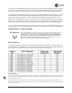
Table 3-1. Channel/Frequency Allocations • Channel 1.75 MHz B/W 10 921.400000 11 923.400000 12 925.200000 13 927.000000 3.5 MHz B/W RF Bandwidth—View/set the radio’s RF operating bandwidth. Radios are factory-configured for either 1.75 MHz or 3.5 MHz maximum bandwidth. Determine the factory configuration of a radio by viewing the “CONFIG” number on the label at the bottom of the radio. 1.75 MHz units will have a Configuration string starting with HGA/R9N1, and 3.
using Offset 0. The hand-off configured Remote, using its AP Locations file, may connect to AP1, AP2, or AP3. The Remote does this by determining the Offset for each AP, then configuring its radio. AP 1 Pattern A Offset 0 AP 2 Pattern A Offset 1 RM Static Hopping Offset 0 • • • • • • • Hand-Off Mode Parameters 05-4446A01, Rev. C AP 3 Pattern A Offset 2 RM Hopping w/ Hand-offs Current AP—Shows the name of the AP that the Remote is trying to associate with.
hand-off parameters for Remote transceivers and explains how they operate under different signal conditions. Table 3-2. Remote Hand-Off Parameters Strict Distance Strict Connection Strict Signal Signal and Distance Signal, Distance, and Bearing Description The Remote always chooses the closest AP regardless of connection status, RSSI, etc. The Remote will only choose a new AP when the modem link is lost.
Advanced Configuration Menu Invisible place holder Figure 3-31. Advanced Configuration Menu • Adaptive Modulation—Enables automatic selection of modulation and FEC rate based on SNR. [enabled, disabled; enabled] • Protection Margin—A • • • • • number of decibels of SNR added to the minimum SNR required for a given modulation and FEC rate. See “Modulation Protection and Hysteresis Margins” on Page 66 for more information.
• ARQ—Enables the Automatic [enable, disable; enabled] • ARQ Window Size—The • • • • • • Modulation Protection and Hysteresis Margins Repeat Request function. maximum number of blocks to send before receiving an acknowledgement. [1–1024; 512] ARQ Block Size—ARQ is applied to payload data in blocks of this size. [4–2040; 256] ARQ Block Lifetime—ARQ blocks are valid for this length of time.
For example, the third SNR value in Column D is 11.4 dB (8.4 + 3 = 11.4 dB), and the third SNR value in Column E is 17.1 (11.1 + 3 + 3 = 17.1 dB). Note that with a Hysteresis Margin of 3 dB, there is an overlap of 3 between the Max SNR of one modulation and the Min SNR of the next higher modulation. In this case, if a link is operating with an SNR of 15 dB, then QPSK-3/4 modulation is used. The SNR must go above 17.1 dB before the link shifts up to 16QAM-1/2 modulation.
NOTE: To restore the COM1 port to support Management System services, connect a terminal to the port, select the proper baud rate (115,200 is default), and enter an escape sequence (+++) to reset it to the console mode. There is a configuration parameter for the console baud rate and another parameter for the serial data baud rate. These items can be different, so when switching out of data mode to console mode, the port might also change its baud rate. TCP vs.
UDP Multicast IP provides a mechanism to perform a limited broadcast to a specific group of devices. This is known as multicast addressing. Multicast addressing requires the use of a specific branch of IP addresses set apart by the Internet Assigned Numbers Authority (IANA) for this purpose. UDP multicast is generally used to transport polling protocols typically used in SCADA applications where multiple remote devices will receive and process the same poll message.
Figure 3-33. Serial Configuration Wizard • Begin Wizard—Tool for configuring serial ports using a step-by-step process. • View Current Settings—Displays all setable options. Varies depending on the selected IP protocol. Configuring for UDP Point-to-Multipoint Invisible place holder Figure 3-34. UDP Point-to-Multipoint Menu Use UDP point-to-multipoint to send a copy of the same packet to multiple destinations, such as in a polling protocol. • • 70 Status—Enable/Disable the serial data port.
• • • • • • • • • 05-4446A01, Rev. C RX IP Port—Receive IP data from this source and pass it through to the connected serial device. The port number must be used by the application connecting to local TCP or UDP socket. [Any valid IP port; 30010] TX IP Address (used instead of Local IP Address when using UDP Point-to-Multipoint)— Configure with a valid Multicast address (224.0.0.0–239.255.255.255). IP packets received with a matching destination address are processed by this unit.
Invisible place holder Figure 3-35. UDP Point-to-Point Menu Configuring for UDP Point-to-Point Use UDP point-to-point configuration to send information to a single device. • • • • • • • • 72 Status—Enable/Disable the serial data port. IP Protocol—UDP Point-to-Point. This is the type of IP port offered by the transceiver’s serial device server. [TCP, UDP; TCP] Remote IP Address—Data received through the serial port is sent to this IP address.
• Commit Changes and Exit Wizard—Save and execute changes made on this screen (shown only after changes have been entered). Configuring for TCP Mode Invisible place holder Figure 3-36. TCP Client Menu (Remote) • • • • • • • • • 05-4446A01, Rev. C Status—Enable/Disable the serial data port. IP Protocol—TCP Client. This is the type of IP port offered by the transceiver’s serial device server.
• Buffer Size—Maximum amount of characters that the Remote end buffers locally before transmitting data through the serial port. [1–255; 255] • Inter-Frame Packet Delay—A measurement representing the end of a message, measured in tenths of a second. [default = 1 (that is, 1/10th of a second)] • Commit Changes and Exit Wizard—Save and execute changes made on this screen (shown only after changes have been entered). Invisible place holder Figure 3-37.
• Commit Changes and Exit Wizard—Save and execute changes made on this screen (shown only after changes have been entered). IP-to-Serial Application Example You must choose UDP or TCP to establish communications. This depends on the type of device you are communicating with at the other end of the IP network. In this example, we will use TCP to illustrate its use. In TCP mode, the transceiver remains in a passive mode, offering a socket for connection.
Point-to-Point Serial-to-Serial Application Example Once you have configured the transceivers, they begin processing data presented at the COM ports. Data presented at the Access Point’s COM port is packetized and sent via UDP to the Remote. Upon receiving the packet, the Remote strips the data out of the UDP packet and sends it out its COM port. Likewise, data presented at the Remote’s COM port is packetized, sent to the Access Point, stripped, and sent out the Access Point’s COM port.
Access Point, stripped, and sent out the Access Point’s COM port (see Figure 3-40, Table 3-6, Figure 3-41, and Figure 3-42 on Page 78). Invisible place holder 192.168.0.2 192.168.0.10 LA N 192.168.0.1 COM 1 EIA-232 COM 2 PW R LIN K Remote RTU 192.168.0.3 EIA-232 LA N COM 1 EIA-232 COM 2 PW R Terminal or Computer LIN K Access Point RTU Remote LA N COM 1 EIA-232 COM 2 PW R LIN K 192.168.0.4 Remote RTU Figure 3-40.
Figure 3-41. Serial Port Configuration—Access Point Figure 3-42. Radio Serial Port Configuration—Remote Mixed Modes In this example, the TCP mode does not involve the Access Point. Thus, the transceiver in a single network can run in both modes at the same time. In other words, you can configure some Remotes for TCP mode and others (along with the Access Point) for UDP mode. In this configuration, the Host PC can use both data paths to reach the RTUs.
Operation and Data Flow • Communicate with RTU A by Telneting to Remote 1, port 30010. • Communicate with RTU B by Telneting to Remote 2, port 30010. • Communicate with RTUs C and D by sending and receiving data from the Access Point’s COM port. • All communication paths can be used simultaneously.
Table 3-7. Serial Port Application Configuration (Continued) Transceiver Location Menu Item Setting Receive on Port 30010 Receive on Address 224.254.1.1 (The multicast IP address used for the AP’s Send To Address above) 3.6 MODBUS / TCP SERVER CONFIGURATION Modbus is a serial communications protocol developed by Schneider Electric (Modicon) for communication between programmable logic controllers (PLCs), remote terminal units (RTUs) and other industrial electronic devices.
management system. Follow the steps below to proceed with Modbus/TCP configuration. 1. From the Serial Configuration Wizard opening screen (Figure 3-44 on Page 81), select A to begin the wizard. Invisible place holder Figure 3-44. Configuration Wizard Opening Screen 2. Choose the IP protocol you wish to use (TCP, UDP, or Modbus/TCP) by selecting the appropriate letter from the menu. Figure 3-45. IP Protocol Selection Screen 3.
Figure 3-46. Modbus/TCP Server Listening Port 4. On the next screen (Figure 3-47), press A to change the Modbus serial format, then press the space bar to toggle between the available formats (MODBUS/RTU or MODBUS/ASCII). Press B to enter the Modbus serial timeout value in milliseconds. Press N to continue the wizard. NOTE: The only difference between Modbus/RTU and Modbus/ASCII is the form of the framing sequence, error check pattern, and address interpretation. Figure 3-47.
5. When the next screen appears (Figure 3-48), press A to select the desired data baud rate and B to select the data byte format. Press N to continue. Figure 3-48. Select Data Baud Rate and Byte Format 6. The screen shown in Figure 3-49 appears next. Press A to select the Buffer Size of message packets, and B to select the Inter-Frame Delay. Press N to continue with the wizard. Invisible place holder Figure 3-49. Buffer Size and Inter-Frame Delay Values 7.
Invisible place holder Figure 3-50. Serial Port Status Screen 8. Review all settings on the summary screen shown in Figure 3-51. If all settings are correct, press X to confirm and exit the wizard. If not, select the letter of the item(s) you wish to change. Invisible place holder Figure 3-51. Serial Configuration—Summary Screen This completes the menu selections for Modbus/TCP operation. 84 Mercury Reference Manual 05-4446A01, Rev.
3.7 SECURITY CONFIGURATION MENU The transceiver’s security features are grouped into four major categories and are accessible from the Security Configuration Menu (see Figure 3-52). These categories are: Device Security—Contains settings for controlling access to the radio itself for configuration and management. Wireless Security—Controls how and when radios communicate with each other, as well as how data traffic is handled. RADIUS Configuration—Deals with IEEE 802.
3.7.1 Device Security Menu The Device Security Menu (Figure 3-53) controls how the radios can be accessed either locally or remotely for configuration and management. Invisible place holder Figure 3-53. Device Security Menu • Telnet Access—Controls Telnet access to the agement system. [enabled, disabled; enabled] • SSH Access—Controls access [enabled, disabled; enabled] • HTTP Mode—Controls • • • • 86 transceiver’s man- to the Secure Shell (SSH) server.
User Passwords Menu Invisible place holder Figure 3-54. User Passwords Menu To change the Administrator or Guest password, select the appropriate menu item (A or B). A flashing cursor appears to the right. From here, type the new password, which can be any alpha-numeric string up to 13 characters long. The change is asserted when you press the Return key. • Change Admin Password—Allows you to set a new [any alpha-numeric string up to 13 characters; admin] password.
Invisible place holder Figure 3-55. Wireless Security Menu • Device Auth Mode—View/set the device’s authentication method. [None, Local, IEEE 802.1X; None] • Data Encryption—Controls the over-the-air payload data’s AES-128 bit encryption. [enable, disable; disabled] • Encryption Phrase—View/set the phrase used to generate encryption keys when encrypting over-the-air payload.
Invisible place holder Figure 3-56. Approved Remotes Submenu • Add Remote—Enter the MAC address of Remote. [Any valid 6-digit hexadecimal MAC address; 00:00:00:00:00:00] • Delete Remote—Enter the MAC address of Remote. For security purposes, you should delete a stolen or deprovisioned radio from this list. • Add Associated Remotes—Add all currently associated remotes to the approved remote list. Alternatively, you can enter each Remote MAC manually.
Each Access Point and Remote radio must be identified/recognized by the device authentication server through the Common Name (Serial number) and IP address entries. NOTE: Consult your network administrator for assistance in configuration, or for help with other issues that may arise. To activate device authentication, select Device Auth Method and set RADIUS as the active mode. The behavior of this setting differs depending on whether it is implemented on an Access Point or a Remote transceiver.
RADIUS Configuration Menu Invisible place holder Figure 3-57. Radius Configuration Menu • Auth Server Address—The IP address server. [any valid IP address; 0.0.0.0] • Auth Server Port—The [1812, 1645, 1812] • Auth Server Shared Secret—User of the authentication UDP Port of the authentication server. authentication and Device authentication require a common shared secret to complete an authentication transaction.
Invisible place holder Figure 3-58. Manage Certificates Menu • TFTP Host Address—(Telnet/Terminal only)—IP address of the com- puter on which the TFTP server resides. This same IP address is used in other screens/functions (reprogramming, logging, etc.). Changing it here also changes it for other screens/functions. [Any valid IP address; 127.0.0.1]. • Transfer Options—A menu for configuring the TFTP transfer. (See Figure 3-59 on Page 93.
Invisible place holder Figure 3-59. Transfer Options Menu • TFTP Timeout—The time the client radio will wait for a response from the server before ending the transfer. • TFTP Block Size—The amount of data sent in each TFTP packet. 3.8 REDUNDANCY CONFIGURATION (AP ONLY) For operation in protected (redundant) mode, an AP must be in a Packaged P23 enclosure with a backup radio. See MDS publication 05-4161A01 for details. This manual is available under the Downloads tab at www.GEmds.com.
Invisible place holder Figure 3-60. Redundancy Configuration Menu (AP Only) • Redundancy Configuration—Enable/disable ver for AP. [enabled, disabled; disabled] • Network Event Triggers—This • • • • 94 redundancy switcho- selection opens a submenu (Figure 3-61 on Page 95) where you can set/view the trigger status for Network Events.
Network Event Triggers Menu Invisible place holder Figure 3-61. Network Events Triggers Menu • Network Interface Error—This setting determines whether or not a network interface error will cause redundancy switchover. [enabled, disabled; disabled] Radio Event Triggers Invisible place holder Figure 3-62. Radio Event Triggers • setting determines whether or not a switchover occurs when a lack of associated Remote units exceeds the time period set in Figure 3-65 on Page 97.
Hardware Event Triggers Invisible place holder Figure 3-63. Hardware Event Triggers • Init/Hardware Error—This setting determines whether or not an initialization or hardware error results in a redundancy switchover. [enabled, disabled; disabled] Redundancy Configuration Options Menu Use this menu (Figure 3-64) to set the thresholds for the Lack of Associated Remotes and Packet Receive Errors. Selecting either item opens a submenu where you can view or change settings.
• Packet Receive Errors Exceeded Threshold—This selection opens a submenu (Figure 3-66 on Page 97) where you can view or change the maximum allowable number of receive errors. Lack of Associated Remotes Exceeded Threshold Menu Invisible place holder Figure 3-65. Lack of Associated Remotes Exceeded Threshold Menu • Packet Receive Errors Exceeded Threshold Menu Lack of Remotes for—Select this item to change the time setting (in seconds) for a lack of associated Remotes.
• 3.9 Maximum Receive Errors—Select this item to change the maximum allowable number of receive errors. When the number of errors exceeds this number, a redundancy switchover occurs. [0-1000; 500] GPS CONFIGURATION (REMOTE ONLY) This menu allows you to view or set important parameters for the built-in Global Positioning System (GPS) receiver in the Mercury Remote. Invisible place holder Figure 3-67.
Invisible place holder Figure 3-68. GPS Streaming Configuration Menu • • • • • • • • 05-4446A01, Rev. C GGA Polling—Seconds between GGA string outputs, the satellite fix information. GLL Polling—Seconds between GLL string outputs, the latitude and longitude information. GSA Polling—Seconds between GSA string outputs, the overall satellite data. GSV Polling—Seconds between GSV string outputs, the detailed satellite data. RMC Polling—Seconds between RMC string outputs, the recommended minimum data.
3.10 DEVICE INFORMATION MENU Figure 3-69 shows the menu that displays basic administrative data on the unit to which you are connected. It also provides access to user-specific parameters such as date/time settings and device names. Figure 3-69. Device Information Menu • • • • • • • • 100 Model (Display only) Serial Number (Display only) Uptime (Display only)—Elapsed time since boot-up. Date—Current date being used for the transceiver logs. User-setable.
• Device Names—Fields used at user’s discretion for general administrative purposes. The Device Name field is shown on all menu screen headings. (See Figure 3-70 on Page 101) NOTE: The transceivers do not save time and date information when power is removed. Device Names Menu Figure 3-70. Device Names Menu • Device Name—Used by the transceiver as the “Realm” name for network login (web browser only) and menu headings. • Contact—User defined; appears on this screen only.
Invisible place holder Figure 3-71. Performance Information Menu • • • • • • • 102 Event Log—Access this menu for managing the unit’s operational activities log. (See Figure 3-74 on Page 104 for details.) Packet Statistics—Multiple radio and network operating statistics. (See Figure 3-76 on Page 106 for details.) GPS Status—Shows satellite fix status, number of satellites being received, and unit location data. (See Figure 3-77 on Page 107 for details.
Invisible place holder Figure 3-72. Performance Trend Screen Invisible place holder Figure 3-73. Bridge Status Menu 05-4446A01, Rev.
Event Log Menu Invisible place holder Figure 3-74. Event Log Menu • Current Alarms—Shows active alarms (if any) reported by the • View Event Log—Displays a log of radio events arranged by event transceiver. • • • • • • 104 number, date, and time. (Example shown in Figure 3-75 on Page 105). Clear Event Log—Erases all previously logged events. Send Event Log—Sends the event log to the server. You must answer the challenge question Send File? y/n before the request proceeds.
View Event Log Menu Invisible place holder Figure 3-75. View Event Log Menu The transceiver’s microprocessor monitors many operational parameters and logs them. Events are classified into four levels of importance, which are described in Table 3-8. Some of these events result from a condition that prevents normal operation of the unit. These are “critical” events that cause the unit to enter an “alarmed” state and the PWR LED to blink until the condition is corrected.
Invisible place holder Figure 3-76. Packet Statistics Menu • • • • • • • • • 106 Packets Received—Data packets received by this unit. Packets Sent—Data packets sent by this unit. Bytes Received—Data bytes received by this unit. Bytes Sent—Data bytes sent by this unit. Packets Dropped—To-be-transmitted packets dropped because of a lack of buffers in the outbound queue. Receive Errors—Packets that do not pass CRC.
GPS Status Menu Invisible place holder Figure 3-77. GPS Status Menu • GPS Serial Number—The serial number of the GPS unit in the • GPS Firmware Version—The • Satellite Fix Status—Indicates radio. firmware version running on the GPS chip. • • • • • 05-4446A01, Rev. C whether or not the unit has achieved signal lock with the minimum required number of GPS satellites. The transceiver requires a fix on five satellites to achieve Precise Positioning Service (PPS) and four to maintain PPS.
GPS Information Menu Invisible place holder Figure 3-78. GPS Information Menu Wireless Network Status Menu The Wireless Network Status screen provides information on a key operating process of the transceiver—the association of the Remote with the Access Point. The following is a description of how this process takes place and is monitored by the menu system.
Invisible place holder Figure 3-79. Wireless Network Status Menu (AP) Invisible place holder Figure 3-80. Wireless Network Status Menu (Remote) • Device Status—Displays the overall transceiver. [Operational, Alarmed] • Associated Remotes operating condition of the (AP Only)—Shows the number of Remote transceivers currently associated with the AP. • PA Temperature—Shows the power amplifier temperature in degrees Celsius.
• • • • • (Remote Only)—Displays the current state of the wireless network communication as follows: Scanning, Ranging, Connecting, Authenticating, Associated, or Alarmed. A complete explanation of these operating states is provided in Table 4-3 on Page 138. Current AP Eth Address—Displays the Ethernet MAC address of the current AP. Current AP IP Address—Shows the IP address of the current AP. Current AP Name—Displays the device name of the current AP.
Invisible place holder Figure 3-83. Remote Database Details Menu (AP) Internal Radio Status Menu (Remote Only) Invisible place holder Figure 3-84. Internal Radio Status (Remote Only) • whether or not the Remote station has associated with an AP. [Associated, Scanning, Ranging, Connecting, Authorizing] • Current AP Name—Shows the Device Name of the current AP. • Transmit Power—Shows the RF power output from the transmitter.
• Average SNR—Shows average signal-to-noise-ratio (SNR) of received signals, displayed in dB. This is a measurement of the quality of the incoming signal. It is possible for incoming signals to be strong, yet be affected by interference or other noise, resulting in a low SNR. Use this parameter to help determine the actual quality of signals. • Radio Details—This selection presents a screen (Figure 3-85) showing key operating details of the transceiver. Invisible place holder Figure 3-85.
3.12 MAINTENANCE/TOOLS MENU In the course of operating your network, you may wish to upgrade transceiver firmware to take advantage of product improvements, work with configuration scripts, conduct “ping” tests of your system, or reset operating parameters to factory default settings. All of these tasks are performed using the Maintenance/Tools Menu (Figure 3-86). This section explains how to take advantage of these services. Invisible place holder Figure 3-86.
Invisible place holder Figure 3-87. Firmware Versions Menu Figure 3-88. Telnet Utility Menu • • Host Address—The Connect—Connect IP address of the target device. to the target device at the host address. Reprogramming Menu The factory sometimes offers upgrades to the transceiver firmware.
NOTE: Always read the release notes for downloaded firmware. These notes contain important information on compatibility and any special steps needed for proper installation. All units and versions have two resident images. Version 1.4.4 had two .mpk files, one for the Access Point and one for the Remote. As of version 2.1.0, there is only one .mpk file which you can use with both Access Points and Remotes.
• Reboot Device—Initiates rebooting of the transceiver. This will interrupt data traffic through this unit, and the network if performed on an Access Point. Intended to be used for switching between firmware images 1 and 2. • Current Firmware—Displays the versions of firmware images installed in the transceiver and shows whether Image 1 or Image 2 is currently active. NOTE: See Upgrade Procedure on Page 117 for details on setting up the TFTP server. Firmware images are available free-of-charge at: www.
Invisible place holder TRANSCEIVER LOCAL WINDOWS PC WITH CONFIG. FILES TP R TFRVE ET E S TELN & CROSS-O VE RC ABL E LAN PORT IP ADDRESS: 172.0.0.B IP ADDRESS: 172.0.0.A INITIATE UPLOAD FROM HERE Figure 3-90. Firmware Upgrade Setup—Option 1 (TFTP Server and Firmware File on Same CPU) Invisible place holder REMOTE PC W/FIRMWARE FILES TFTP SERVER HUB/LAN/WAN/MAN TCP/IP ETHERNET PORT IP ADDRESS: 172.0.0.A TRANSCEIVER IP ADDRESS: 172.0.0.B LAN PORT LOCAL WINDOWS PC COM1, 2, ETC.
1. Launch a TFTP server on a PC connected either directly or via a LAN to the Ethernet port (LAN) of the radio. Point the server towards the directory containing the firmware image file. 2. Connect to the Management System by whichever means is convenient: browser or Telnet via the LAN, or Terminal emulator via the COM1 port. 3. Go to the MS Reprogramming Menu. (Main Menu>>Maintenance Menu>>Reprogramming Menu) 4.
Table 3-9. Common Errors During TFTP Transfer (Continued) Error Message Likely Cause/Corrective Action Flash Error Flash memory error. Contact factory for assistance. Bad CRC Cyclic Redundancy Check reporting a corrupted file. Attempt to re-load, or use a different file. Version String Mismatch Invalid file detected. Attempt to re-load, or use a different file.
Invisible place holder Figure 3-92. Configuration Scripts Menu • TFTP Host Address—IP address of the computer on which the TFTP server resides. [Any valid IP address] • Config Filename—Name of file containing this unit’s configuration profile that will be transferred to the TFTP server. The configuration information is in plain-text ASCII format. [Any 40-character alphanumeric string] May require a sub-directory, for example: config\mercury-config.txt.
Editing Configuration Files Once a Remote unit’s operation is fine-tuned, use the Configuration Scripts Menu on Page 119 to save a copy of the configuration onto a PC. Once the file is saved on the PC, you can use it as a source to generate modified copies adjusted to match other devices. Modify the configuration files using a text editor or an automated process. (These applications are not provided by GE MDS). We recommend that you review and update the following parameters for each individual unit.
Ping Utility Menu Invisible place holder Figure 3-93. Ping Utility Menu • • • • Address to Ping—Address to send a Ping. [Any valid IP address] of Ping packets to be sent. Packet Size—Size of each Ping data packet (bytes). Ping—Send Ping packets to address shown on screen. Count—Number This screen is replaced with a detailed report of Ping activity (see example in Figure 3-94). Press any key after viewing the results to return to this menu. Invisible place holder Figure 3-94.
Authorization Codes Invisible place holder Figure 3-95. Authorization Codes Menu • Authorization Key—For entering an Authorization Key into the transceiver’s non-volatile memory. • Authorized Features—List of the transceiver’s authorized features. Each item shows enabled or disabled according to the settings allowed by the Authorization Key entered into the radio.
Invisible place holder Figure 3-96. Reset to Factory Defaults Action (Note challenge question at bottom of screen) 3.12.1Auto Firmware Upgrade Menu (AP Only) Invisible place holder Figure 3-97.Auto Firmware Upgrade Menu • all of the Remotes associated to this AP to read the AP’s specified (by Firmware for Upgrade) firmware version (active or inactive), and download it via TFTP to the inactive image if the Remote does not already have that firmware version.
NOTE: To use the Auto Upgrade/Reboot feature, both the AP and Remotes must already be running version 2.1.0 or newer firmware. • Firmware for Upgrade—Specifies the firmware version that the Remotes should download, if they do not already have it. Radio Test Menu Using this menu, you can manually key the radio transmitter for performance checks and set several parameters that will be used when the Radio Mode is set to Test. Invisible place holder Figure 3-98.
• Test Transmit Power—Sets/displays the transmitter’s power setting. Make a numerical entry within the allowable range. [-30 to +30 dBm] • Test Channel—Sets/displays the radio’s test channel number. Make a numerical entry within the allowable range. [0-13; 0] • Test RF Bandwidth—Sets/displays the transmitter’s bandwidth for testing. Use the Spacebar to view selections. [1.75. 3.5 MHz; 1.75 MHz] • Test Burst Percentage—Sets/displays the percentage of Burst size to use for testing.
Figure 3-100. Spectrum Analyzer Display 3.13 PERFORMANCE OPTIMIZATION After checking basic radio operation, you can optimize the network’s performance. The effectiveness of these techniques varies with the design of your system and the format of the data being sent. There are two major areas for possible improvement—the radio and the data network. These sections provide a variety of items to check in both categories, and in many cases, ways to improve performance.
Table 3-11. Recommended Settings for Common Scenarios For Fixed Locations, where best combination of range and throughput is desired. Remote User discretion User discretion Transmit Power (AP)/ Max Transmit Power (RM) 30 30 dBm In most cases, power can be set to +30 dBm and left alone. Setting it lower helps control cell overlap. Receive Power -70 N/A dBm Sets AP receiver for medium gain. Typical range: -60, -80 dBm.
For Optimal Sensitivity (Trades off throughput for best possible sensitivity. AP more susceptible to interference) Radio Configuration Receive Power AP Remote Units Notes -80 N/A dBm Sets AP receiver for highest gain. When Heavy Interference Exists at AP (Trades off range for robustness in the face of interference) Radio Configuration Receive Power AP Remote Units -60 N/A dBm Notes Sets AP receiver for low gain, which forces Remote transmit power to be high.
Table 3-12. Mercury Remote Transceiver (Continued) (Performance Information>>Internal Radio Status Menu) Name Target Value Notes SNR (Signal-to-Noise Ratio) Strong signal (bench setting): 25-28 dB A low SNR may be caused by noise or interfering signals. Operational: 3-30 dB Typ. System: 10-20 dB TX Freq. Offset 0-22,875 Hz Adjusts to accommodate what is expected by the AP. RX Freq. Offset 0-22,875 Hz Adjusts to accommodate what is expected by the AP.
Additional Considerations for Mobile Operation Consider the following key points for all mobile installations: • Use connectionware—The use of connectionware in the mobile laptops is highly recommended for better operation of a mobile data system. GE MDS provides connectionware from one of the vendors in this market. Contact your factory representative for details. • Plan your network coverage—Deploy Access Points so that they provide overlapping coverage with each other.
132 Mercury Reference Manual 05-4446A01, Rev.
4 TROUBLESHOOTING & RADIO MEASUREMENTS 4 Chapter Counter Reset Paragraph Contents 4.1 TROUBLESHOOTING ............................................................ 135 4.1.1 4.1.2 4.1.3 4.1.4 4.1.5 4.1.6 Interpreting the Front Panel LEDs .............................................135 Troubleshooting Using the Embedded Management System ...136 Using Logged Operation Events ...............................................139 Alarm Conditions ...............................................................
134 Mercury Reference Manual 05-4446A01, Rev.
4.1 TROUBLESHOOTING Successful troubleshooting of a wireless system is not difficult, but requires a logical approach. It is best to begin troubleshooting at the Access Point unit, as the rest of the system depends on the Access Point for synchronization data. If the Access Point has problems, the operation of the entire wireless network is affected. When you find communication problems, it is good practice to begin by checking the simple causes.
resolving common system difficulties using the LEDs, and Table 4-2 on Page 137 provides other simple techniques. Table 4-1. Troubleshooting Using LEDs—Symptom-Based Symptom Problem/Recommended System Checks PWR LED does not turn on a. Voltage too low—Check for the proper supply voltage at the power connector. (10–30 Vdc) b. Indefinite Problem—Cycle the power and wait (≈ 30 seconds) for the unit to reboot. Then, recheck for normal operation. LINK LED does not turn on a.
Table 4-2. Basic Troubleshooting Using the Management System Symptom Problem/Recommended System Checks Cannot access the MS through COM1 a. Connect to unit via Telnet or Web browser. b. Disable the serial mode for COM1 (Serial Gateway Configuration>>Com1 Serial Data Port>>Status>>Disabled). Or, if you know the unit’s data configuration: a. Connect to COM 1 via a terminal set to VT100 and the port’s data baud rate. b. Type +++. c.
connect to the Management System, see “STEP 3—CONNECT PC TO THE TRANSCEIVER” on Page 23. Starting Information Screen (See Starting Information Screen on Page 40) The Management System’s home page provides some valuable bits of data. One of the most important is the Device Status field. This item tells you if the unit is operational. If the Device Status field says Associated, then look in the network areas beginning with network data statistics.
Packet Statistics Menu (See Packet Statistics Menu on Page 105) This screen provides detailed information on data exchanges between the unit being viewed and the network through the wireless and the Ethernet (data) layers.
permanent memory (Flash memory) until cleared by user request. Table 4-4 summarizes these classifications. Table 4-4.
Table 4-5. Alarm Conditions (Alphabetical Order) (Continued) Alarm Condition Reported Event Log Entry SNMP Trap EVENT_RSSI_CAL RSSI Not Calibrated rssiCal(9) EVENT_SYSTEM_ERROR* System Error Cleared; Please Reboot systemError(16) EVENT_TFTP_CONN TFTP connectivity achieved tftpConnection(73) EVENT_TFTP_ERR Attempted TFTP connection failed tftpConnFailed(79) * User can correct condition, clearing the alarm. 4.1.
4.1.6 Logged Events (See Event Log Menu on Page 104) The following events allow the transceiver to continue operation and do not make the PWR LED blink. Each is reported through an SNMP trap. The left hand column, Event Log Entry, is what shows in the Event Log. Table 4-7.
Table 4-7. Non-Critical Events—Alphabetical Order (Continued) Event Log Entry Severity Description SNR Within threshold/Below threshold INFORM Self explanatory System Bootup (power on) INFORM Self explanatory Telnet Access Locked for 5 Min MAJOR Self explanatory Telnet User Logged Out/Logged In MAJOR Self explanatory User Selected Reboot MAJOR Self explanatory 4.2 RADIO (RF) MEASUREMENTS There are several measurements that should be performed during the initial installation.
Record the current transmitter power output level, then set it to 30 dBm for the duration of the test to provide an adequate signal level for the directional wattmeter. Procedure 1. Place a directional wattmeter between the TX antenna connector and the antenna system. 2. Place the transceiver into the Radio Test Mode using the menu sequence below: (Maintenance/Tools Menu>>Radio Test>>Radio Mode>>Test) 3. Set the transmit power to 30 dBm.
strength. The transceiver has a built-in received signal strength indicator (RSSI) that can tell you when the antenna is in a position that provides the optimum received signal. RSSI measurements and Wireless Packet Statistics are based on multiple samples over a period of several seconds. The average of these measurements is displayed by the Management System. The measurement and antenna alignment process usually takes 10 or more minutes at each radio unit.
7. If the RSSI peak results in an increase in the Wireless Packets Dropped and Received Error, the antenna may be aimed at an undesired signal source. Try a different antenna orientation. End of procedure. 146 Mercury Reference Manual 05-4446A01, Rev.
5 PLANNING A RADIO NETWORK 5 Chapter Counter Reset Paragraph Contents 5.1 INSTALLATION PLANNING .................................................... 149 5.1.1 5.1.2 5.1.3 5.1.4 5.1.5 5.1.6 5.1.7 General Requirements ..............................................................149 Site Selection ............................................................................151 Terrain and Signal Strength .......................................................151 Antenna & Feedline Selection ..............
148 Mercury Reference Manual 05-4446A01, Rev.
5.1 INSTALLATION PLANNING This section provides tips for selecting an appropriate site, choosing an antenna system, and reducing the chance of harmful interference. 5.1.1 General Requirements There are three main requirements for installing a transceiver—adequate and stable primary power, a good antenna system, and the correct interface between the transceiver and the data device. Figure 5-1 shows a typical Remote installation.
4.5″ (11.43 cm) mounting location that provides easy access to the connectors on the end of the radio and an unobstructed view of the LED status indicators. TOP VIEW 6.75″ (17.15 cm) 1.4″ (3.56 cm) FRONT VIEW Figure 5-2. Transceiver Dimensions 2.75″ (7 cm) Invisible place holder 8 5/8″ (21.8 cm) Figure 5-3. Mounting Bracket Dimensions (center to center) NOTE: To prevent moisture from entering the radio, do not mount the radio with the cable connectors pointing up.
5.1.2 Site Selection Suitable sites should provide: • Protection from direct weather exposure • A source of adequate and stable primary power • Suitable entrances for antenna, interface, or other required cabling • An antenna location that provides a transmission path that is as unobstructed as possible in the direction of the associated station(s) With the exception of the transmission path, you can quickly determine these requirements.
Antennas The radio equipment can be installed with a number of antennas. The exact style used depends on the physical size and layout of a system. Contact your factory representative for specific recommendations on antenna types and hardware sources. In general, an omnidirectional antenna (Figure 5-4) is used at the Access Points and mobile Remote stations. This provides equal signal coverage in all directions. NOTE: Antenna polarization is important.
Invisible place holder Figure 5-5. Typical Yagi Antenna (mounted to mast) Diversity Reception (RX2) Antenna Port Reserved for future functionality. Future releases of the product will allow you to connect a second antenna to the transceiver for space diversity reception. GPS Antennas A number of GPS antennas (both active and passive) are available for use with the transceivers. Consult your factory representative for more information.
cable at 900 MHz. The choice of cable depends on the required length, cost considerations, and the acceptable amount of signal loss. Table 5-1. Length vs. Loss in Coaxial Cables at 900 MHz Cable Type 10 Feet (3.05 m) 50 Feet (15.24 m) 100 Feet (30.48 m) 500 Feet (152.4 m) RG-214 .76 dB 3.8 dB 7.6 dB Unacceptable Loss LMR-400 0.39 dB 1.95 dB 3.90 dB Unacceptable Loss 1/2 inch HELIAX 0.23 dB 1.15 dB 2.29 dB 11.45 dB 7/8 inch HELIAX 0.13 dB 0.64 dB 1.28 dB 6.40 dB 1-1/4 inch HELIAX 0.
NOTE: There is no minimum feedline length required when a 6 dBi gain or less antenna is used, as the EIRP will never exceed 36 dBm which is the maximum allowed, per FCC rules. Only the manufacturer or a sub-contracted professional installer can adjust the transceiver’s RF output power. The transceiver’s power output is factory set to maintain compliance with the FCC’s Digital Transmission System (DTS) Part 15 rules.
reported RSSI value. (See “Antenna Aiming—For Directional Antennas” on Page 144 for details.) If you cannot obtain adequate signal strength, it might be necessary to mount the station antennas higher, use higher gain antennas, select a different site, or install a repeater station.
chance of causing unnecessary interference to nearby systems. If you are not familiar with these interference-control techniques, contact your factory representative for more information. Calculating System Gain To determine the maximum allowable power setting of the radio, perform the following steps: 1. Determine the antenna system gain by subtracting the feedline loss (in dB) from the antenna gain (in dBi). For example, if the antenna gain is 9.5 dBi, and the feedline loss is 1.
5.2 dBm-WATTS-VOLTS CONVERSION CHART Table 5-4 is provided as a convenience for determining the equivalent voltage or wattage of an RF power expressed in dBm. Table 5-4. dBm-Watts-Volts conversion—for 50 ohm systems 158 dBm V Po dBm V Po dBm mV +53 +50 +49 +48 +47 +46 +45 +44 +43 +42 +41 +40 +39 +38 +37 +36 +35 +34 +33 +32 +31 +30 +29 +28 +27 +26 +25 +24 +23 +22 +21 +20 +19 +18 +17 +16 +15 +14 +13 +12 +11 +10 +9 +8 +7 +6 +5 +4 +3 +2 +1 200W 100W 80W 64W 50W 40W 32W 25W 20W 16W 12.5W 10W 8W 6.
6 TECHNICAL REFERENCE 6 Chapter Counter Reset Paragraph Contents 6.1 DATA INTERFACE CONNECTORS ........................................ 161 6.1.1 LAN Port ....................................................................................161 6.1.2 COM1 Port ................................................................................162 6.2 SPECIFICATIONS ................................................................... 162 6.3 NOTES ON SNMP .......................................................
160 Mercury Reference Manual 05-4446A01, Rev.
6.1 DATA INTERFACE CONNECTORS Two types of data interface connectors are provided on the front panel of the transceiver—an RJ-45 LAN port, and a DB-9 serial port (COM1), which uses the RS-232 (EIA-232) signaling standard. CAUTION RADIO FREQUENCY INTERFERENCE POTENTIAL The transceiver meets U.S.A.’s FCC Part 15, Class A limits when used with shielded data cables. 6.1.1 LAN Port Use the transceiver’s LAN port to connect the radio to an Ethernet network.
6.1.2 COM1 Port The COM1 serial port is a DB-9 female connector. Connect a PC to the transceiver via this port with a DB-9M to DB-9F “straight-through” cable. These cables are available commercially, or may be constructed using the pinout information in Figure 6-2 and Table 6-2. 5 9 1 6 Figure 6-2. COM1 Port (DCE) (Viewed from the outside of the unit.) Table 6-2. COM1 Port Pinout, DB-9F/RS-232 Interface 6.
• Sensitivity and Data Rate (see chart below): 3.5 MHz Channel Modulation (CP=1/16) Sensitivity Signaling Rate 1.75 MHz Channel Max. User Throughput (Aggregate)* Sensitivity Signaling Rate Max. User Throughput (Aggregate)* 64 QAM 3/4 FEC -77 dBm 12.7 Mbps 7.2 Mbps -80 dBm 6.35 Mbps 3.6 Mbps 16 QAM 3/4 FEC -86 dBm 8.4 Mbps 4.8 Mbps -89.5 dBm 4.2 Mbps 2.4 Mbps QPSK 3/4 FEC -92 dBm 4.2 Mbps 2.4 Mbps -95 dBm 2.1 Mbps 1.2 Mbps BPSK 1/2 FEC -95 dBm 1.
Electrical • Input Power: 10-30 Vdc • Current Consumption (nominal): Mode Power 13.8 Vdc 24 Vdc AP Transmit 25 W 1.8 A 1.0 A AP Receive 8W 579 mA 333 mA RM Transmit 25W 1.8 mA 1.0 A RM Receive 6.5W 471 mA 270 mA Mechanical • Case: Die Cast Aluminum • Dimensions: 5.715 H x 20 W x 12.382 D cm. (2.25 H x 7.875 W x 4.875 D in.) • Weight: 1kg (2.2 lb.
6.3 NOTES ON SNMP 6.3.1 Overview The firmware release described in this manual contains changes to the transceiver’s SNMP Agent, several new MIB variables, and new Agent configuration options. This guide reviews the changes and shows how to properly configure the Agent to take advantage of these new features. SNMPv3 Support The updated SNMP Agent now supports SNMP version 3 (SNMPv3).
Admin accounts: context_a/Viewer accounts: context_v. All accounts share the same default passwords: Authentication default password: MDSAuthPwd/Privacy default password: MDSPrivPwd. Passwords can be changed either locally (via the console) or from an SNMP Manager, depending on how the Agent is configured. If passwords are configured and managed locally, they are non-volatile and will survive a power-cycle.
• Passwords are currently managed locally. The local passwords are Fairport (Auth) and Churchville (Priv). Configuration is changed to handle the passwords from the Manager. The same passwords will continue to be used, but now the Manager can change them. • Passwords are currently managed locally. The local passwords are Fairport (Auth) and Churchville (Priv). Passwords are changed to Brighton (Auth) and Perinton (Priv).
Table 6-3.
7 GLOSSARY OF TERMS AND ABBREVIATIONS 7 Chapter Counter Reset Paragraph If you are new to wireless IP/Ethernet systems, some of the terms used in this manual might be unfamiliar. The following glossary explains many of these terms and will prove helpful in understanding the operation of your radio network. Some of these terms do not appear in the manual, but are often encountered in the wireless industry, and are therefore provided for completeness.
from the number and order of bits in a data string. This value is compared with a locally-generated value and a match indicates that the message is unchanged, and therefore valid. Data Circuit-terminating Equipment—See DCE. Data Communications Equipment—See DCE. Datagram—A data string consisting of an IP header and the IP message within. Data Terminal Equipment—See DTE. dBd—Decibels (dipole antenna). dBi—Decibels referenced to an “ideal” isotropic radiator in free space.
Digital Signal Processing—See DSP. DSP—Digital Signal Processing. DSP circuitry is responsible for the most critical real-time tasks; primarily modulation, demodulation, and servicing of the data port. DTE—Data Terminal Equipment. A device that provides data in the form of digital signals at its output. Connects to the DCE device.
communications device. When the buffer approaches overflow, the radio drops the clear-to-send (CTS) line, that instructs the connected device to delay further transmission until CTS again returns to the high state. Host Computer—The computer installed at the master station site, that controls the collection of data from one or more remote sites.
and tear down connections with various access points as it moves through the access points' territory. Mode—See Device Mode. MTBF—Mean-Time Between Failures Multiple Address System (MAS)—See Point-Multipoint System. NMEA—National Marine Electronics Association. National body that established a protocol for interfacing GPS data between electronic equipment. Network Name—User-selectable alphanumeric string that is used to identify a group of radio units that form a communications network.
Portability refers to the ability of a station to connect to an access point from multiple locations without the need to reconfigure the network settings. For example, a remote transceiver that is connected to an access point may be turned off, moved to new site, turned back on, and, assuming the right information is entered, can immediately reconnect to the access point without user intervention. PLC—Programmable Logic Controller.
SNTP—Simple Network Time Protocol SSL—Secure Socket Layer SSH—Secure Shell STP—Spanning Tree Protocol Standing-Wave Ratio—See SWR. SWR—Standing-Wave Ratio. A parameter related to the ratio between forward transmitter power and the reflected power from the antenna system. As a general guideline, reflected power should not exceed 10% of the forward power (≈ 2:1 SWR).
176 Mercury Reference Manual 05-4446A01, Rev.
INDEX Numerics 100BaseT 51, 149 10BaseT 51, 149 16QAM 67 64QAM 67 802.
BPDU 53 defined 169 BPS, defined 169 BPSK 67 Bridge Configuration 43 Forward Delay 53 Hello Time 53 Priority 52 Protocol Data Unit 53 Bridge Status 102 Buffer Size 71, 74 BW 56 Byte Format 71 byte format 72, 74 bytes defined 169 received 106 sent 106 C cable crossover 34, 36, 161 EIA-232 Shielded Data 18 Ethernet crossover 13, 23, 37 Ethernet RJ-45 Crossover 17 Ethernet RJ-45 Straight-thru 18 feedlines 153 serial communications 23, 35 straight-through 36, 37, 161 certificate files 89 type 92 Certificate Fil
Delete All Remotes 89 Remote 89 Delimiter, defined 170 deployment costs 11 Description 101 Device Auth Mode 88 Authentication 89 Information 42 Menu 100 Mode 40 defined 170 Name 40, 101, 121 Security Menu 86 Status 40, 109, 138 messages 138 DHCP 50 defined 170 DNS address 49 ending address 49 Netmask 49 Server 46 Config 46, 47 Configuration 43, 44 Status 49 starting address 49 WINS address 49 Diagnostic Tools 139 dimensions 149 DIN Rail Mounting Bracket 18 DKEY command 143 Downlink 130 Percentage 66 DSP (Di
G gain antenna, defined 169 system 157 gateway current IP 50 Glossary 169–175 GPS antenna 153 Configuration 42 defined 171 external GPS PPS option 7, 164 Firmware Version 107 information 107 latitude 56 longitude 56 Precise Positioning Service 107 pseudo-random noise 107 receiver 40 satellite fix 57 Serial Number 107 Status 102 Menu 107 Streaming Configuration 98 time of day 57 timing signals 40 to Console Baud Rate 98 UDP Server IP Address 98 UDP Server UDP Port 98 GROUP 57 H hand-off 63 Signal and Distanc
Latency, defined 172 Latitude 107 LED COM1 26 LAN 26, 36, 37, 136 LINK 26, 27, 136, 145, 155 PWR 26, 105, 136, 140, 142 use during troubleshooting 135 Local Area Network, defined 172 Console 34 session 35 IP Port 72 Listening IP Port 74 Location 101, 121 logged events 142 LONG 56 Longitude 107 Lost Carrier Detected 106, 139 M MAC 56 ADDR 130 Main Menu 42 Maintenance/Tools 43 Menu 113 Manage Certificates 85 Management VLAN ID 46 VLAN Mode 46 VLAN Subnet Config 46 Management System 23, 67, 118 as a troublesho
packets dropped 106, 139 received 106 sent 106 password admin 87 guest 87 Pattern Offset 131 PC connection to transceiver 23 host 78 peer-to-peer communications 8 Performance Information 43 Trend 102 PING 21, 26, 113, 155 address 122 defined 173 utility 113 PKI 173 PLC 11 defined 174 point-to-multipoint 14 defined 173 Point-to-Point LAN Extension 9 Link 9 Poll, defined 173 port access 45, 46 COM1 12, 23, 24, 25, 31, 34, 36, 42, 67, 75, 80, 117, 118, 151, 161, 162 COM2 24, 75 Ethernet 21, 45, 46 GPS antenna
Remote add 89 associated 89 approved 88 Database 109 delete 89 all 89 IP Address 72 Port 72 Max 6 Performance Database 109 radio, defined 174 Standard 6 Terminal Unit 11 defined 174 view approved 89 Repeater 12 antennas 13 Network Name 13 Using the AP as a Store-and-Forward Packet Repeater 14 Using two transceivers to form a repeater station 12 Reprogramming 113 Menu 114 Reset to Factory Defaults 113, 123 Retries 139 Retrieve Certificate 92 File 115, 120 Retry errors 139 RF bandwidth 24, 62 Output Power 24
SSH 34, 90 Access 86 defined 175 SSL, defined 175 Standing Wave Ratio 175 Starting Information Screen 36, 42 Static IP Address 46, 47, 50 Gateway 51 Netmask 46, 47, 51 Status 40, 70, 72, 73, 74 alarmed 138 associated 138 authenticating 138 connecting 138 scanning 138 STP, defined 175 Stream GPS to Console 98 subnet 51 SWR 143, 175 defined 175 performance optimization 143 Syslog Server Address 104 system gain, antenna (defined) 169 T tabletop network 21 Talkback Enable 71 TCP 68, 78 client 68 defined 175 ser
volts-dBm-watts conversion 158 W watts-dBm-volts conversion 158 Web browser 34, 67 session 37 Wireless LAN 8 Network Status 102 Menu 108 Security 85 Menu 87 wizard serial configuration 69 Write community String 54 Y Yagi antenna 153 05-4446A01, Rev.
I-10 Mercury Reference Manual 05-4446A01, Rev.
IN CASE OF DIFFICULTY... GE MDS products are designed for long life and trouble-free operation. However, this equipment, as with all electronic equipment, may have an occasional component failure. The following information will assist you in the event that servicing becomes necessary. TECHNICAL ASSISTANCE Technical assistance for GE MDS products is available from our Technical Support Department during business hours (8:00 A.M.–5:30 P.M. Eastern Time).
GE MDS, LLC 175 Science Parkway Rochester, NY 14620 General Business: +1 585 242-9600 FAX: +1 585 242-9620 Web: www.GEmds.