
User's Manual


05-4446A01, Rev. C Mercury Reference Manual 157
chance of causing unnecessary interference to nearby systems.
If you are not familiar with these interference-control techniques, con-
tact your factory representative for more information.
Calculating System Gain
To determine the maximum allowable power setting of the radio, per-
form the following steps:
1. Determine the antenna system gain by subtracting the feedline loss
(in dB) from the antenna gain (in dBi). For example, if the antenna
gain is 9.5 dBi, and the feedline loss is 1.5 dB, the antenna system
gain would be 8 dB. (If the antenna system gain is 6 dB or less, no
power adjustment is required.)
2. Subtract the antenna system gain from 36 dBm (the maximum
allowable EIRP). The result indicates the maximum transmitter
power (in dBm) allowed under the rules. In the example above, this
is 28 dBm.
3. If the maximum transmitter power allowed is less than 30 dBm, set
the power to the desired level using the Management System.
(Main Menu>>Radio Configuration>>Transmit Power)
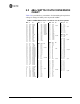
For convenience,
Table 5-3 lists several antenna system gains and
shows the maximum allowable power setting of the radio. Note that a
gain of 6 dB or less entitles you to operate the radio at full power output
–30 dBm.
For assistance in the conversion of dBm to Watts, see
dBm-WATTS-VOLTS CONVERSION CHART on Page 158.
* Most antenna manufacturers rate antenna gain in dBd in their litera-
ture. To convert to dBi, add 2.15 dB.
** Must use with the appropriate length of feedline cable to reduce
transmitter power by at least 2 dB.
† Feedline loss varies by cable type and length. To determine the loss
for common lengths of feedline, see Table 5-1 on Page 154.
Table 5-3. Examples of Antenna System Gain
vs. Power Output Setting
Antenna System Gain
(Antenna Gain in dBi*
minus Feedline Loss in dB†)
Maximum Power Setting
(PWR command)
EIRP
(in dBm)
Omni 6 (or less) 30 36
Omni 9 27 36
Yagi 12 24 36
Yagi 14 22 36
Yagi 16 20 36
Panel 17.4** 20 36