MDS Mercury Series TM Wireless IP/Ethernet Transceiver Covering AP and Remote Units DRAFT MDS 05-4446A01, Rev. 03 SEPT. 2008 Reference Manual Microwave Data Systems Inc.
TABLE OF CONTENTS 1 PRODUCT OVERVIEW AND APPLICATIONS............ 1 1.1 ABOUT THIS MANUAL......................................................................................................... 3 1.1.1 Start-Up Guide ...........................................................................................................................3 1.1.2 Online Access to Manuals ..........................................................................................................3 1.1.
2.4 STEP 3—CONNECT PC TO THE TRANSCEIVER............................................................ 23 2.5 STEP 4—REVIEW TRANSCEIVER CONFIGURATION .................................................... 23 2.5.1 Getting Started .........................................................................................................................23 2.5.2 Procedure .................................................................................................................................23 2.5.
3.7.3 IEEE 802.1x Device Authentication ..........................................................................................89 3.7.4 Manage Certificates .................................................................................................................91 3.8 REDUNDANCY CONFIGURATION (AP ONLY) ................................................................. 93 3.9 GPS CONFIGURATION (REMOTE ONLY) ........................................................................ 98 3.
5.1.7 A Word About Radio Interference ...........................................................................................156 5.2 dBm-WATTS-VOLTS CONVERSION CHART .................................................................. 158 6 TECHNICAL REFERENCE..................................... 159 6.1 DATA INTERFACE CONNECTORS ................................................................................. 161 6.1.1 LAN Port ...........................................................................
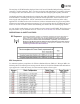
The majority of GE MDS radios deployed since 1985 are still installed and performing within our customers’ wireless networks. That s because we design and manufacture our products in-house, according to ISO 9001 which allows us to control and meet stringent global quality standards.
CSA/us Notice This product is approved for use in Class 1, Division 2, Groups A, B, C & D Hazardous Locations. Such locations are defined in Article 500 of the National Fire Protection Association (NFPA) publication NFPA 70, otherwise known as the National Electrical Code. The transceiver has been recognized for use in these hazardous locations by the Canadian Standards Association (CSA) which also issues the US mark of approval (CSA/US). The CSA Certification is in accordance with CSA STD C22.2 No.
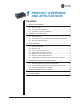
1 PRODUCT OVERVIEW AND APPLICATIONS 1 Chapter Counter Reset Paragraph Contents 1.1 ABOUT THIS MANUAL ............................................................... 3 1.1.1 Start-Up Guide .............................................................................. 3 1.1.2 Online Access to Manuals ............................................................. 3 1.1.3 Conventions Used in This Manual ................................................ 3 1.2 PRODUCT DESCRIPTION ..............................
2 Mercury Reference Manual 05-4446A01, Rev.
1.1 ABOUT THIS MANUAL This Reference Manual is one of two publications provided for users of the Mercury SeriesTM transceiver system. It contains detailed product information, an overview of common applications, a screen-by-screen review of the menu system, technical specifications, suggested settings for various scenarios, and detailed troubleshooting information. This manual should be available to all personnel responsible for network design, setup, commissioning and troubleshooting. 1.1.
Menu Strings To help show the path to a menu selection, navigation strings are used in several places in this manual. For example, suppose you want to view or set the Network Name assigned to your system. This item is located in the Network Configuration Menu, so the navigation string in the text would appear as shown: Main Menu>>Network Configuration>>Network Name By following this order of menus, you can quickly reach the desired menu. 1.
Simple Installation Mercury Transceivers are designed for rapid and trouble-free installation. For basic services, you simply connect the antennas (3650 MHz and GPS, as required), connect your data equipment, apply primary power, and set some operating parameters. No license is required for operation in the USA, Canada, and many other countries. Check requirements for your region before placing the equipment into service.
The text-based interfaces (RS-232 console, Telnet, and SSH) are implemented in the form of easy-to-follow menus, and the terminal server provides a wizard to help you configure the units correctly. Transceiver Features The transceiver s design makes the installation and configuration easy, while allowing for future changes. ¥ Industrial-Grade Product Extended temperature range for trouble-free operation in extreme environments.
In addition to gasket color, a label on the top of each radio identifies it as an AP or Remote unit. If the label shows an —Asuffix, it is an AP. If it shows a —Rsuffix, it is a Remote. 1.2.2 GE MDS P23 Protected Network (Redundant) Configuration For mission-critical applications, a Protected Network Station is also offered. This unit incorporates two Access Points, two power supplies, and a switchover logic board that automatically selects between Transceiver A and Transceiver B as the active radio.
1.3.1 Fixed Data System Mercury transceivers support high-speed data communications in an industrial environment. In this application, Remote radios roam between different Access Points, providing seamless transitions and continuous coverage throughout a municipal area. 1.3.2 Wireless LAN The wireless LAN is a common application of the transceiver. It consists of a central control station (Access Point) and one or more associated Remote units, as shown in Figure 1-4.
Invisible place holder Remote Access Point LAN/WAN LAN Figure 1-4. Typical Point-to-Point Link 1.3.4 Serial Radio Network Connectivity The transceiver provides a path for serial devices to migrate to IP/Ethernet systems. Many radio networks in operation today still rely on serial networks at data rates of 9600 bps or less. These networks can use the transceiver as a means to continue using the serial service, while allowing the infrastructure to migrate to an IP format.
Invisible place holder Remote Serial RTU EIA-232 Flow Meter SCADA Host Modbus/IP EIA-232 Remote Serial HUB HUB EIA-232 Serial Device EIA-232 Serial Device EIA-232 Serial Device EIA-232 Serial Device Access Point WAN ROUTER Remote Serial HUB HUB Access Point NETview SCADA Host Total Flow Figure 1-6. Multiple Protocol Network By using a single radio, the cost of deployment is cut in half.
video, security monitoring, and Voice over IP. Figure 1-8 shows a typical wireless IP network. Invisible place holder Remote Bridge IP Camera IP/Ethernet Access Point Remote Bridge IP/Ethernet NMS Control Point SCADA Host Modbus/IP IP/Ethernet Printer Figure 1-7. Extended-Range LAN with Mixed Applications 1.3.
1.4 NETWORK DESIGN CONSIDERATIONS 1.4.1 Extending Network Coverage with Repeaters What is a Repeater System? A repeater works by re-transmitting data from outlying remote sites to the Access Point, and vice-versa. It introduces some additional end-to-end transmission delay but provides longer-range connectivity. In some geographical areas, obstacles can make communications difficult. These obstacles are commonly large buildings, hills, or dense foliage.
by the repeater station antennas. A detailed discussion on the effects of terrain is given in Section 5.1.2, Site Selection (beginning on Page 151). The following paragraphs contain specific requirements for repeater systems. Antennas Two antennas are required at this type of repeater station one for each radio. You must take measures to minimize the chance of interference between these antennas. One effective technique for limiting interference is to employ vertical separation.
Invisible place holder Remote Remote LAN Remote Access Point REPEATER LAN LAN/WAN Remote LAN Figure 1-9. Typical Store-and-Forward Repeater Arrangement As with the conventional repeater described in Option 1 above, the location of a store and forward repeater is also important. A site must be chosen that allows good communication with both the Access Point and the outlying Remote site.
The Network Name and the Association Process The Network Name is the foundation for building individual radio networks. Remotes in a network with the same network name as an Access Point (AP) unit are associated with that AP. The use of a different Network Name does not guarantee an interference-free system. It does, however, assure that only data destined for a unique network is passed through to that network.
The transceiver is capable of dealing with many common security issues. Table 1-2 profiles security risks and how the transceiver provides a solution for minimizing vulnerability. Table 1-2. Security Risk Management Security Vulnerability GE MDS Cyber Security Solution Unauthorized access to the backbone network through a foreign remote radio • IEEE 802.
1.6 ACCESSORIES The transceiver can be used with one or more of the accessories listed in Table 1-3. Contact the factory for ordering details. Table 1-3. Accessories Accessory Description GE MDS Part No. AC Power Adapter Kit A small power supply module designed for continuous service. UL approved. Input: 120/220; Output: 13.8 Vdc @ 2.5 A 01-3682A02 OmniDirectional Antennas Rugged antennas well suited for use at Access Point installations.
Table 1-3. Accessories (Continued) 18 Accessory Description GE MDS Part No. DIN Rail Mounting Bracket Bracket used to mount the transceiver to standard 35 mm DIN rails commonly found in equipment cabinets and panels. 03-4022A03 COM1 Interface Adapter DB-25(F) to DB-9(M) shielded cable assembly 97-3035A06 (6 ft./1.8 m) for connection of equipment or other EIA-232 serial devices previously connected to legacy units. (Consult factory for other lengths and variations.
2 TABLETOP EVALUATION AND TEST SETUP 2 Chapter Counter Reset Paragraph Contents 2.1 OVERVIEW ............................................................................... 21 2.2 STEP 1 CONNECT THE ANTENNA PORTS.......................... 21 2.3 STEP 2 CONNECT THE PRIMARY POWER ......................... 22 2.4 STEP 3 CONNECT PC TO THE TRANSCEIVER................... 23 2.5 STEP 4 REVIEW TRANSCEIVER CONFIGURATION ........... 23 2.5.1 Getting Started ........................................................
20 Mercury Reference Manual 05-4446A01, Rev.
2.1 OVERVIEW GE MDS recommends that you set up a tabletop network to verify the basic operation of the transceivers. This allows experimenting with network designs, configurations, or network equipment in a convenient location. This test can be performed with any number of radios. When you are satisfied that the network is functioning properly in a benchtop setting, perform the field installation.
NOTE: Use attenuation between all units in the test setup. The amount of attenuation required depends on the number of units tested and the desired signal strength (RSSI) at each transceiver during the test. In no case should a signal greater than —50 dBm be applied to any transceiver in the test setup. GE MDS recommends an RF power output level of +20 dBm from the AP. Remote power is not setable. (See Radio Configuration Menu on Page 58.) 2.
2.4 STEP 3 CONNECT PC TO THE TRANSCEIVER Connect a PC s Ethernet port to theLAN port using an Ethernet crossover cable. The LAN LED should light. Alternatively, you can use a serial cable to connect to the COM1 port (Figure 2-3 on Page 25). 2.5 STEP 4 REVIEW TRANSCEIVER CONFIGURATION 2.5.1 Getting Started Start by logging into the Access Point radio. This is done first because the Remotes are dependent on the AP s beacon signal to achieve an associated state.
Table 2-1. Basic Configuration Defaults Item Menu Location Default Values/Range Network Name Main Menu>> Radio Configuration>> Network Name MDS-Mercury ¥ 1—15 alphanumeric characters IP Address Main Menu>> Network Configuration>> IP Address 192.168.1.1 Contact your network administrator RF Output Power Main Menu>> Radio Configuration>> Transmit Power +30 dBm (1.0 Watt) AP: -30 to +30 dBm RM: 0 to +30 dBm (Max. 1.
Invisible place holder LAN PORT LED INDICATOR PANEL COM1 SERIAL PORT DC POWER INPUT (10—30 VDC, 2.5A) RX2 ANTENNA PORT GPS ANTENNA TX/RX1 CONNECTION ANTENNA PORT Figure 2-3. Transceiver Interface Connectors ¥ LED INDICATOR PANEL Displays the basic operating status of the transceiver. Section 2.7 on page 26 contains detailed information. ¥ COM1 SERIAL PORT DB-9 connector used for management of the transceiver using a connected PC. MS INTRODUCTION on Page 31 provides complete connection details.
2.7 STEP 6 CHECK FOR NORMAL OPERATION Once the data equipment is connected, you can check the transceiver for normal operation. Observe the LEDs on the top cover for the proper indications.
Table 2-2. Transceiver LED Functions (Continued) LED Label Activity Indication GPS ON Internal GPS receiver is synchronized with the satellite network. Blinking AP modem is synchronizing with the GPS timing. OFF Internal GPS receiver is not synchronized with the satellite network. LINK ON Default state (Access Point) OFF Not transmitting. Usually occurs while waiting for GPS sync.
28 Mercury Reference Manual 05-4446A01, Rev.
3 EMBEDDED MANAGEMENT SYSTEM 3 Chapter Counter Reset Paragraph Contents 3.1 MS INTRODUCTION................................................................. 31 3.1.1 Differences in the User Interfaces ............................................... 31 3.2 ACCESSING THE MENU SYSTEM .......................................... 33 3.2.1 Methods of Control ...................................................................... 34 3.2.2 PC Connection and Log In Procedures ......................................
3.9 GPS CONFIGURATION (REMOTE ONLY)............................... 98 3.10 DEVICE INFORMATION MENU............................................ 100 3.11 PERFORMANCE INFORMATION MENU ............................. 101 3.12 MAINTENANCE/TOOLS MENU............................................ 113 3.12.1 Auto Firmware Upgrade Menu (AP Only) ................................124 3.13 PERFORMANCE OPTIMIZATION ........................................ 127 3.13.1 Proper Operation What to Look For ........................
3.1 MS INTRODUCTION The transceiver s embedded management system is accessible through the COM1 (serial) port, the LAN (Ethernet) port, and using over-the-air Ethernet. Telnet, SSH, HTTP/HTTPS, and SNMP are the Ethernet-based interfaces. Essentially, the same capabilities are available through any of these paths. For support of SNMP software, a set of MIB files is available for download from the GE MDS Web site at www.GEmds.com.
Figure 3-1. Embedded Management System Top-Level Flowchart 32 Mercury Reference Manual 05-4446A01, Rev. C Radio Test Performance Trend Date Format Force Switchover Adv. Config. AP Location Info (RM) NOTES • Chart shows top-level view only. See Reference Manual for details.
Figure 3-2. View of MS with a text-based program (Console Terminal shown Telnet has similar appearance) Invisible place holder Figure 3-3. View of the MS with a Browser (Selections at left provide links to the various menus) 3.2 ACCESSING THE MENU SYSTEM The radio has no external controls or adjustments. All configuration, diagnostics, and control is performed electronically using a connected PC. This section explains how to connect a PC, log into the unit, and gain access to the built-in menus.
3.2.1 Methods of Control Access the unit s configuration menus in one of several ways: ¥ Local Console This is the primary method used for the examples in this manual. Connect a PC directly to the COM1 port using a serial communications cable and launch a terminal communications program such as HyperTerminal (found on most PCs by selecting Start>>Programs>>Accessories>>Communications>>HyperTerminal). This method provides text-based access to the unit s menu screens.
Invisible place holder Transceiver To COM1 or LAN Port (see text) PC Running Terminal Session (115,200 bps, 8N1) Figure 3-4. PC Configuration Setup Starting a Local Console Session (Recommended for first-time log-in) 1. Connect a serial communications cable between the PC and the unit sCOM1 port. If necessary, a cable may be constructed for this purpose as shown in Figure 3-5.
5. Enter your password (default password is admin). For security, your password keystrokes do not appear on the screen. Press ENTER . NOTE: Passwords are case sensitive. Do not use punctuation mark characters. You may use up to 13 alpha-numeric characters. The unit responds with the Starting Information Screen (Figure 3-6). From here, you can review basic information about the unit or press G to proceed to the Main Menu. Invisible place holder Figure 3-6.
TIP: You can start a Telnet session on most PCs by selecting: Start>>Programs>>Accessories>>Command Prompt. At the command prompt window, type the word telnet, followed by the unit s IP address (e.g., telnet 10.1.1.168). Press ENTER to receive the Telnet log in screen. NOTE: Never connect multiple units to a network with the same IP address. Address conflicts will result in improper operation. 3. Enter your username (default username is admin). Press ENTER . Next, the Password: prompt appears.
Invisible place holder Figure 3-7. Log-in Screen when using a Web Browser NOTE: Passwords are case sensitive. Do not use punctuation mark characters. You may use up to 13 alpha-numeric characters. 5. Click OK. The unit responds with a startup menu screen similar to that shown in Figure 3-8. From here, you can review basic information about the unit or click one of the menu items at the left side of the screen. Invisible place holder Figure 3-8. Starting Information Screen Web Browser Example 3.2.
associated screen where settings may be viewed or changed. In most cases, pressing the ESCAPE key moves the screen back one level in the menu tree. In general, the top portion of menu screens show read-only information (with no user selection letter). The bottom portion of the screen contains parameters you can select for further information, alteration of values, or to navigate to other submenus. NOTE: Early versions of PuTTY might not operate when using SSH to connect to the transceiver.
NOTE: In the menu descriptions that follow, parameter options/range, and any default values are displayed at the end of the text between square brackets. Note that the default setting is always shown after a semicolon: [available settings or range; default setting] 3.3 BASIC OVERVIEW OF OPERATION 3.3.1 Starting Information Screen Once you have logged into the Management System, the Starting Information Screen (Figure 3-9) appears with an overview of the transceiver and its current operating conditions.
¥ The unit is has detected one or more alarms that have not been cleared. Alarmed At Remote: ¥ Scanning The unit is looking for an Access Point beacon signal. ¥ Ranging Unit is adjusting power, timing, and frequency with an AP. ¥ Connecting The unit has found a valid beacon signal for its network. ¥ Authenticating Device is attempting device authentication. ¥ Associated The unit has successfully synchronized and associated with an Access Point.
3.3.2 Main Menu The Main Menu is the entry point for all user-controllable features. The transceiver sDevice Name appears at the top of this and all other screens as a reminder of the unit you are currently controlling. Figure 3-10. Main Menu (AP) (AP screen shown; Remote similar, differences noted below) ¥ ¥ ¥ ¥ ¥ ¥ ¥ ¥ 42 Select this item to return to the Starting Information screen described above. Network Configuration Tools for configuring the data network layer of the transceiver.
¥ Status information relating to the radio and data layer s performance in the radio network. (See PERFORMANCE INFORMATION MENU on Page 101) ¥ Maintenance/Tools Tools for upgrading firmware code and testing major unit capabilities. (See MAINTENANCE/TOOLS MENU on Page 113) Performance Information 3.4 CONFIGURING NETWORK PARAMETERS 3.4.
¥ Presents a submenu for configuring an AP to automatically force connected remotes to receive the AP Locations file from the AP. See AP Location Push Config Menu on Page 55 for details. ¥ SNTP Server Address of SNTP server (RFC 2030) from which the transceiver will automatically get the time-of-day. You can also manually set the date and time. A Mercury unit tries to get the time and date from the SNTP server only if an IP address is configured. It will continue to retry every minute until it succeeds.
VLAN Configuration Menu The VLAN Configuration menu (Figure 3-13) becomes active and visible when you enable VLAN Status on the Network Interface Configuration Menu, and you press the Enter key. CAUTION:The VLAN Status parameter must be consistent at both the Access Point and Remote radios in order for data to flow correctly. Failure to do so might result in data not being transported correctly even when the radios are in an associated state and able to communicate over-the-air.
Network Interface Configuration Menu VLAN Items Invisible place holder Figure 3-13. VLAN Configuration Menu ¥ ¥ ¥ ¥ ¥ ¥ ¥ ¥ 46 Defines whether the radio handles Ethernet frames in extended 802.1Q mode or in normal mode in the Ethernet port. If configured with a trunk port, the Mercury passes all tagged traffic regardless of the VLAN ID. The Mercury only uses the Data VLAN ID parameter when the ETH port is configured as an Access Port.
¥ Presents a screen where you can view or set the IP mode and address information (see Figure 3-17 on Page 49). ¥ DHCP Server Config (Data) Presents a screen where you can view or set DHCP server status and address information for data functions (see Figure 3-16 on Page 49). Data VLAN Subnet Config Management VLAN Subnet Configuration Menu Invisible place holder Figure 3-14.
DHCP Server Configuration (Data and Mgmt) A transceiver can provide automatic IP address assignments to other IP devices in the network by providing DHCP (Dynamic Host Configuration Protocol) services. This service eliminates setting an individual device IP address on Remotes in the network, but it requires some planning of the IP address range. One drawback to network-wide automatic IP address assignments is that SNMP services might become inaccessible as they are dependent on fixed IP addresses.
Invisible place holder Figure 3-16. DHCP Server Configuration (Data) Menu ¥ ¥ ¥ ¥ ¥ ¥ Data VLAN Subnet Configuration Menu Enable/Disable the response to DHCP requests to assign an IP address. [Disabled/Enabled; Disabled] DHCP Netmask IP netmask to be assigned along with the IP address in response to a DHCP request. [0.0.0.0] DHCP starting address Lowest IP address in the range of addresses provided by this device. [0.0.0.
¥ Defines the source of this device s IP address. Only static IP addressing mode is available when VLAN Status is enabled [Static; Static] ¥ IP Address The IPv4 local IP address. [ 192.168.1.1] ¥ IP Netmask The IPv4 local subnet mask. This value is used when the radio attempts to send a locally initiated message, from either the terminal server or the management process. [255.255.0.0] ¥ IP Gateway The IPv4 address of the default gateway device, typically a router. [0.0.0.
¥ The IPv4 local subnet mask. This field is unnecessary if DHCP is enabled. [255.255.0.0] ¥ Static IP Gateway The IPv4 address of the network gateway device, typically a router. This field is unnecessary if DHCP is enabled. [0.0.0.0] Static IP Netmask The lower three items on the screen (Current IP Address, Netmask and Gateway) show the actual addressing at the transceiver whether it was obtained from static configuration or from a DHCP server. 3.4.
¥ Allows enabling/disabling filtering and specifying of Ethernet addresses. Ethernet Filtering Config Ethernet Filtering Configuration Menu Invisible place holder Figure 3-20. Ethernet Filtering Configuration Menu ¥ Enable Filtering Activates Ethernet [enabled, disabled; disabled] ¥ Address 1, 2, 3, 4 filtering. Ethernet address fields. When filtering is enabled, the Mercury only accepts traffic on its Ethernet port from the configured addresses. [Valid IP address string] 3.4.
¥ View/set spanning tree hello time. This parameter affects how often the bridge sends a spanning tree Bridge Protocol Data Unit (BPDU). [1-10 seconds; 2 seconds] ¥ Bridge Forward Delay View/set spanning tree forwarding delay. Affects how long the bridge spends listening and learning after initialization. [4-30 seconds; 5 seconds]. Bridge Hello Time 3.4.
Invisible place holder Figure 3-22. SNMP Server Configuration Menu This menu provides configuration and control of vital SNMP functions. ¥ ¥ ¥ ¥ ¥ ¥ 54 SNMP community name with SNMPv1/SNMPv2c read access. This string can contain up to 30 alpha-numeric characters. Write Community String SNMP community name with SNMPv1/SNMPv2c write access. This string can contain up to 30 alpha-numeric characters. Trap Community String SNMP community name with SNMPv1/SNMPv2c trap access.