Wireless IP/Ethernet Transceiver Covering all AP and Remote Units including Mercury 900, 3650, and Option Set 1 Remotes 05-4446A01, Rev.
TABLE OF CONTENTS 1 PRODUCT OVERVIEW & APPLICATIONS ............ 1 1.1 ABOUT THIS MANUAL................................................................................................... 3 1.1.1 Start-Up Guide .................................................................................................................... 3 1.1.2 Online Access to Manuals ................................................................................................... 3 1.1.3 Conventions Used in This Manual ...........
2.4 STEP 3: CONNECT PC TO THE TRANSCEIVER ....................................................... 25 2.5 STEP 4: REVIEW TRANSCEIVER CONFIGURATION ................................................ 25 2.5.1 Getting Started .................................................................................................................. 25 2.5.2 Procedure .......................................................................................................................... 25 2.5.
3.7.2 Wireless Security Menu ..................................................................................................... 95 3.7.3 IEEE 802.1x Device Authentication ................................................................................... 97 3.7.4 Manage Certificates .......................................................................................................... 99 3.8 REDUNDANCY CONFIGURATION (AP ONLY) ......................................................... 102 3.
.1.8 ERP Compliance at 900 MHz .......................................................................................... 172 5.1.9 ERP Compliance at 3650 MHz ........................................................................................ 173 5.2 dBm-WATTS-VOLTS CONVERSION CHART ............................................................ 174 6 TECHNICAL REFERENCE.................................... 175 6.1 DATA INTERFACE CONNECTORS ...............................................................
The majority of GE MDS radios deployed since 1985 are still installed and performing within our customers' wireless networks. That’s because we design and manufacture our products in-house, according to ISO 9001 which allows us to control and meet stringent global quality standards.
CSA/us Notice (Remote Transceiver Only) This product is approved for use in Class 1, Division 2, Groups A, B, C & D Hazardous Locations. Such locations are defined in Article 500 of the National Fire Protection Association (NFPA) publication NFPA 70, otherwise known as the National Electrical Code. The transceiver has been recognized for use in these hazardous locations by the Canadian Standards Association (CSA) which also issues the US mark of approval (CSA/US).
Industry Canada RSS Notices Operation is subject to the following two conditions: (1) this device may not cause interference, and (2) this device must accept any interference, including interference that may cause undesired operation of the device. To reduce potential radio interference to other users, the antenna type and its gain should be chosen so that the Equivalent Isotropic Radiated Power (EIRP) is not more than that permitted for successful communication.
viii Mercury Reference Manual 05-4446A01, Rev.
1 PRODUCT OVERVIEW AND APPLICATIONS 1 Chapter Counter Reset Paragraph Contents 1.1 ABOUT THIS MANUAL ......................................................... 3 1.1.1 Start-Up Guide ....................................................................... 3 1.1.2 Online Access to Manuals ...................................................... 3 1.1.3 Conventions Used in This Manual ......................................... 3 1.2 PRODUCT DESCRIPTION ................................................... 4 1.
2 Mercury Reference Manual 05-4446A01, Rev.
1.1 ABOUT THIS MANUAL This Reference Manual is one of two publications provided for users of the Mercury SeriesTM transceiver system. It contains detailed product information, an overview of common applications, a screen-by-screen review of the menu system, technical specifications, suggested settings for various scenarios, and troubleshooting information. This manual should be available to all personnel responsible for network design, setup, commissioning and troubleshooting of the radios. 1.1.
Menu Strings To help show the path to a menu selection, navigation strings are used in several places in this manual. For example, suppose you want to view or set the Network Name assigned to your system. This item is located in the Network Configuration Menu, so the navigation string in the text would appear as shown: Main Menu>>Network Configuration>>Network Name By following this order of menus, you can quickly reach the desired menu. 1.
one enclosure contains all necessary components for radio operation and data communications. Simple Installation Mercury Transceivers are designed for rapid and trouble-free installation. For basic services, you simply connect the antennas (900 or 3650 MHz as required, and GPS), connect your data equipment, apply primary power, and set some operating parameters. No license is required for 900 MHz operation in the USA, Canada, and many other countries.
serial/EIA-232-based hardware to the faster and more easily interfaced Ethernet protocol. Flexible Management You can locally or remotely configure, commission, troubleshoot, and maintain the transceiver. Four different modes of access are available: local RS-232 console terminal, local or remote IP access (via Telnet or SSH), web browser (HTTP, HTTPS), and SNMP (v1/v2/v3) All IP access interfaces are available through the unit’s wired Ethernet port and over the air.
Available Frequency Bands At the time of publication, Mercury transceivers are offered in two different frequency bands: 902-928 MHz (Mercury 900) and 3.65–3.70 GHz (Mercury 3650). The 900 MHz unit operates in a license-free spectrum (frequency hopping spread spectrum—FHSS), which may be used by anyone in the USA, provided FCC Part 15 rules are observed. Canada, and certain other countries allow license-free operation in this band—check your country’s requirements. The 3.65–3.
The internal WiFi module has FCC modular approval and may only be operated by connecting one of the GE MDS approved antennas (see 802.11 WiFi Module Specifications below) to the reverse-SMA connector on the radio’s front panel. Only these antennas may be used. The WiFi module can operate as an 802.11 Access Point or Infrastructure Station, according to user configuration. The operational mode (AP, Infrastructure RM) and frequency can be configured through the unit's user interface.
protected chassis. For system-level information on this product, refer to MDS publication 05-4161A01. Invisible place holder Figure 1-3. MDS P23 Protected Network Station (incorporates two transceivers, with automatic switchover) 1.2.4 External GPS PPS Option The External GPS Precise Positioning Service (PPS) option allows for an external GPS device to provide the PPS input to the Mercury. This is useful in installations where multiple radios require GPS timing.
Invisible place holder Mercury remote Mercury AP Video Surveillance RTU/PLC (Ethernet) MDS NETview MS® Computer Mercury remote WAN Long Range WLAN Router RS-232 RTU/PLC (Serial) RS-232 RTU/PLC (Serial) MDS 4710 RS-232 MDS 4790 Master Radio Server (Ethernet) Control Center MDS 4710 Licensed Serial/IP Integration Mercury remote Mercury remote Mobile Data Mobile Data Figure 1-4. Integrated Mobile/Fixed Application 1.3.
1.3.3 Point-to-Point LAN Extension A point-to-point configuration (Figure 1-6) is a simple arrangement consisting of an Access Point and a Remote unit. This provides a communications link for transferring data between two locations. Invisible place holder Remote Access Point LAN/WAN LAN Figure 1-6. Typical Point-to-Point Link 1.3.4 Serial Radio Network Connectivity The transceiver provides a path for serial devices to migrate to IP/Ethernet systems.
to different SCADA hosts). A Mercury radio provides this capability using a single remote unit. The unit’s serial port can be connected via IP to different SCADA hosts, transporting different (or the same) protocols. Both data streams are completely independent, and the transceiver provides seamless simultaneous operation as shown in Figure 1-8.
rower channel to concentrate the radio energy, reaching farther distances. It is designed for industrial operation from the ground up. IP-based devices that may be used with the transceiver include new, powerful Remote Terminal Units (RTUs) and Programmable Logic Controllers (PLCs). These, as well as other devices, may be used in applications ranging from SCADA/telemetry monitoring, web-based video, security monitoring, and Voice over IP. Figure 1-9 shows a typical wireless IP network.
NOTE: Several previous GE MDS-brand products had non-standard signal lines on their interface connectors (for example, to control sleep functions and alarm lines). These special functions are not provided nor supported by the Mercury transceiver. Consult equipment manuals for complete pinout information. 1.4 NETWORK DESIGN CONSIDERATIONS 1.4.
ration is sometimes required in a network that includes a distant Remote that would otherwise be unable to communicate directly with the Access Point station due to distance or terrain. The geographic location of a repeater station is especially important. Choose a site that allows good communication with both the Access Point and the outlying Remote site. This is often on top of a hill, building, or other elevated terrain from which both sites can be “seen” by the repeater station antennas.
Invisible place holder Remote Remote LAN Remote Access Point REPEATER LAN LAN/WAN Remote LAN Figure 1-11. Typical Store-and-Forward Repeater Arrangement As with the conventional repeater described in Option 1 above, the location of a store and forward repeater is also important. A site must be chosen that allows good communication with both the Access Point and the outlying Remote site.
The Network Name and the Association Process The Network Name is the foundation for building individual radio networks. Remotes in a network with the same network name as an Access Point (AP) unit are “associated” with that AP. The use of a different Network Name does not guarantee an interference-free system. It does, however, assure that only data destined for a unique network is passed through to that network.
The transceiver is capable of dealing with many common security issues. Table 1-2 profiles security risks and how the transceiver provides a solution for minimizing vulnerability. Table 1-2. Security Risk Management Security Vulnerability GE MDS Cyber Security Solution Unauthorized access to the backbone network through a foreign remote radio • IEEE 802.
1.6 ACCESSORIES The transceiver can be used with one or more of the accessories listed in Table 1-3. Contact the factory for ordering details. Table 1-3. Accessories Accessory Description GE MDS Part No. AC Power Adapter Kit A small power supply module designed for continuous service. UL approved. Input: 120/220; Output: 13.8 Vdc @ 2.5 A 01-3682A02 OmniDirectional Antennas Rugged antennas well suited for use at Access Point installations.
Table 1-3. Accessories (Continued) 20 Accessory Description GE MDS Part No. DIN Rail Mounting Bracket Bracket used to mount the transceiver to standard 35 mm DIN rails commonly found in equipment cabinets and panels. 03-4022A03 COM1 Interface Adapter DB-25(F) to DB-9(M) shielded cable assembly (6 ft./1.8 m) for connection of equipment or other EIA-232 serial devices previously connected to “legacy” units. (Consult factory for other lengths and variations.
2 TABLETOP EVALUATION AND TEST SETUP 2 Chapter Counter Reset Paragraph Contents 2.1 OVERVIEW ........................................................................... 23 2.2 STEP 1—CONNECT THE ANTENNA PORTS...................... 23 2.3 STEP 2—CONNECT THE PRIMARY POWER ..................... 24 2.4 STEP 3—CONNECT PC TO THE TRANSCEIVER............... 25 2.5 STEP 4—REVIEW TRANSCEIVER CONFIGURATION ....... 25 2.5.1 Getting Started .......................................................................
22 Mercury Reference Manual 05-4446A01, Rev.
2.1 OVERVIEW GE MDS recommends that you set up a “tabletop network” to verify the basic operation of the transceivers. This allows experimenting with network designs, configurations, or network equipment in a convenient location. This test can be performed with any number of radios. When you are satisfied that the network is functioning properly in a benchtop setting, perform the field installation.
NOTE: Use attenuation between all units in the test setup. The amount of attenuation required depends on the number of units tested and the desired signal strength (RSSI) at each transceiver during the test. In no case should a signal greater than –50 dBm be applied to any transceiver in the test setup. GE MDS recommends an RF power output level of +20 dBm from the AP. Remote power is not setable. (See “Radio Configuration Menu” on Page 65.) 2.
2.4 STEP 3: CONNECT PC TO THE TRANSCEIVER Connect a PC’s Ethernet port to the LAN port using an Ethernet crossover cable. The LAN LED should light. Alternatively, you can use a serial cable to connect to the COM1 port (Figure 2-3 on Page 27). 2.5 STEP 4: REVIEW TRANSCEIVER CONFIGURATION 2.5.1 Getting Started Start by logging into the Access Point radio. This is done first because the Remotes are dependent on the AP’s beacon signal to achieve an “associated” state.
Table 2-1. Basic Configuration Defaults Item Menu Location Default Values/Range Network Name Main Menu>> Radio Configuration>> Network Name MDS-Mercury • 1–15 alphanumeric characters IP Address Main Menu>> Network Configuration>> IP Address 192.168.1.
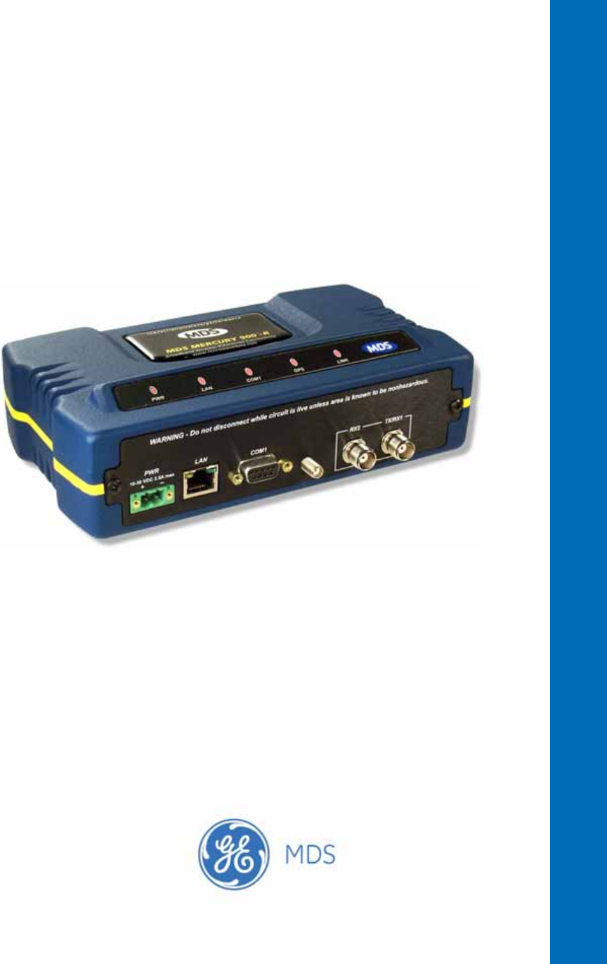
Invisible place holder LAN PORT LED INDICATOR PANEL COM1 SERIAL PORT DC POWER INPUT (10—30 VDC, 2.5A) RX2 ANTENNA PORT GPS ANTENNA TX/RX1 CONNECTION ANTENNA PORT Figure 2-3. Transceiver Interface Connectors (Standard unit shown; See Figure 2-4 on Page 28 for Option Set 1 unit) • LED INDICATOR PANEL—Displays the basic operating status of the transceiver. See section 2.7 on Page 29 for detailed information. • COM1 SERIAL PORT— DB-9 connector used for management of the transceiver with a connected PC.
2.6.1 Option Set 1 Connectors Figure 2-4 shows the interface connectors on the front panel of the Option Set 1 Remote transceiver. NOTE: The use of shielded Ethernet cable is recommended for connection to the radio’s ETH port. The radio meets regulatory emission standards without shielded cable, but shielding reduces the possibility of interference in sensitive environments, and is in keeping with good engineering practice. Invisible place holder Figure 2-4.
• GPS ANTENNA PORT— Coaxial connector (SMA-type) for connection of a GPS receiving antenna. Provides 3.5 Vdc output for compatibility with powered (active) GPS antennas. Do not short this connector, as you might cause damage to the internal power supply. The GPS receiving antenna’s gain must be 16 dBi or less.
If the radio network seems to be operating properly based on observation of the unit’s LEDs, use the PING command to verify the link integrity with the Access Point. Table 2-2.
3 DEVICE MANAGEMENT 3 Chapter Counter Reset Paragraph Contents 3.1 INTRODUCTION ..................................................................... 33 3.1.1 Differences in the User Interfaces ............................................ 33 3.2 ACCESSING THE MENU SYSTEM ........................................ 35 3.2.1 Methods of Control ................................................................... 36 3.2.2 PC Connection and Log In Procedures ................................... 36 3.2.
3.10 DEVICE INFORMATION MENU............................................ 109 3.11 PERFORMANCE INFORMATION MENU ............................. 110 3.12 MAINTENANCE/TOOLS MENU............................................ 123 3.12.1 3.12.2 Installing Firmware via TFTP ................................................ 129 Auto Firmware Upgrade Menu (AP Only) .............................. 138 3.13 PERFORMANCE OPTIMIZATION ........................................ 140 3.13.1 Proper Operation What to Look For .....
3.1 INTRODUCTION The transceiver’s embedded management system is accessible through the COM1 (serial) port, the LAN (Ethernet) port, and using over-the-air Ethernet. Telnet, SSH, HTTP/HTTPS, and SNMP are the Ethernet-based interfaces. Essentially, the same capabilities are available through any of these paths. For support of SNMP software, a set of MIB files is available for download from the GE MDS Web site at www.GEmds.com.
Figure 3-1. Embedded Management System Top-Level Flowchart 34 Mercury Reference Manual 05-4446A01, Rev. E Radio Test Performance Trend Date Format Force Switchover Adv. Config. AP Location Info (RM) NOTES • Chart shows top-level view only. See Reference Manual for details.
Figure 3-2. View of MS with a text-based program (Console Terminal shown Telnet has similar appearance) Invisible place holder Figure 3-3. View of the MS with a Browser (Selections at left provide links to the various menus) 3.2 ACCESSING THE MENU SYSTEM The radio has no external controls or adjustments. All configuration, diagnostics, and control is performed electronically using a connected PC. This section explains how to connect a PC, log into the unit, and gain access to the built-in menus.
3.2.1 Methods of Control Access the unit’s configuration menus in one of several ways: • Local Console—This is the primary method used for the examples in this manual. Connect a PC directly to the COM1 port using a serial communications cable and launch a terminal communications program such as HyperTerminal (found on most PCs by selecting Start>>Programs>>Accessories>>Communications>>HyperTerminal). This method provides text-based access to the unit’s menu screens.
Invisible place holder Transceiver Transceiver To COM1 or LAN Port (See Text) To COM1 or LAN Port (see text) PC Running Terminal Session PC Running Terminal Session (115,200 bps, 8N1) (115,200 bps, 8N1) Figure 3-4. PC Configuration Setup Starting a Local Console Session (Recommended for first-time log-in) 1. Connect a serial communications cable between the PC and the unit’s COM1 port. If necessary, a cable may be constructed for this purpose as shown in Figure 3-5.
5. Enter your password (default password is admin). For security, your password keystrokes do not appear on the screen. Press ENTER . NOTE: Passwords are case sensitive. Do not use punctuation mark characters. You may use up to 13 alpha-numeric characters. The unit responds with the Starting Information Screen (Figure 3-6). From here, you can review basic information about the unit or press G to proceed to the Main Menu. Invisible place holder Figure 3-6.
TIP: You can start a Telnet session on most PCs by selecting: Start>>Programs>>Accessories>>Command Prompt. At the command prompt window, type the word telnet, followed by the unit’s IP address (e.g., telnet 10.1.1.168). Press ENTER to receive the Telnet log in screen. NOTE: Never connect multiple units to a network with the same IP address. Address conflicts will result in improper operation. 3. Enter your username (default username is admin). Press ENTER . Next, the Password: prompt appears.
Invisible place holder Figure 3-7. Log-in Screen when using a Web Browser NOTE: Passwords are case sensitive. Do not use punctuation mark characters. You may use up to 13 alpha-numeric characters. 5. Click OK. The unit responds with a startup menu screen similar to that shown in Figure 3-8. From here, you can review basic information about the unit or click one of the menu items at the left side of the screen. Invisible place holder Figure 3-8. Starting Information Screen Web Browser Example 3.2.
associated screen where settings may be viewed or changed. In most cases, pressing the ESCAPE key moves the screen back one level in the menu tree. In general, the top portion of menu screens show read-only information (with no user selection letter). The bottom portion of the screen contains parameters you can select for further information, alteration of values, or to navigate to other submenus. NOTE: Early versions of PuTTY might not operate when using SSH to connect to the transceiver.
NOTE: In the menu descriptions that follow, parameter options/range, and any default values are displayed at the end of the text between square brackets. Note that the default setting is always shown after a semicolon: [available settings or range; default setting] 3.3 BASIC OVERVIEW OF OPERATION 3.3.1 Starting Information Screen Once you have logged into the Management System, the Starting Information Screen (Figure 3-9) appears with an overview of the transceiver and its current operating conditions.
• Alarmed—The unit has detected one or more alarms that have not been cleared. At Remote: • Scanning—The unit is looking for an Access Point beacon signal. • Ranging—Unit is adjusting power, timing, and frequency with an AP. • Connecting—The unit has found a valid beacon signal for its network. • Authenticating—Device is attempting device authentication. • Associated —The unit has successfully synchronized and associated with an Access Point.
Figure 3-10. Main Menu (AP) (AP menu shown, Remote similar; Differences noted in text below) Figure 3-11. Main Menu (MDS 3650 Remote Only) • Starting Information Screen—Select this item to return to the Start- ing Information screen described above. • Network Configuration—Tools for configuring the data network layer of the transceiver. (See “CONFIGURING NETWORK PARAMETERS” on Page 45) • Radio Configuration—Tools to configure the wireless (radio) layer of the transceiver.
• • • • • • Security Configuration—Tools to configure the security services available with the transceiver’s environment. (See “SECURITY CONFIGURATION MENU” on Page 92) Redundancy Configuration—(AP Only) Allows setting of the criteria for switchover in the event of loss of associated Remotes or excessive packet receive errors. GPS Configuration—(Remote Only; not available on MDS 3650 model) View/set parameters related to GPS streaming location output.
Figure 3-13. Network Configuration Menu (Option Set 1 radio) • • • • • • • 46 Network Interface Config—Presents a menu where you can view or set various parameters (VLAN Status, IP Configuration, and DHCP Server Configuration). Ethernet Port Config—Presents a menu for defining the status of the Ethernet port (enabled or disabled), port follows association, and Ethernet filtering configuration. Detailed explanations of this menu are contained in Ethernet Port Configuration Menu on Page 56.
ceeds. The transceivers use UTC (Universal Time Coordinated) with a configurable time offset. [0] NOTE: The Mercury gets time of day data from the GPS receiver if the receiver gets a satellite fix. Network Interface Configuration Submenu Invisible place holder Figure 3-14. Network Interface Configuration Submenu • VLAN Status—This selection is used to enable or disable virtual LAN operation. For details, refer to VLAN Configuration Menu on Page 47.
About Virtual LAN in Mercury A VLAN is essentially a limited broadcast domain, meaning that all members of a VLAN receive broadcast frames sent by members of the same VLAN but not frames sent by members of a different VLAN. For more information, refer to the IEEE 802.1Q standard. The transceiver supports port-based VLAN at the Ethernet interface and over the air, according to the IEEE 802.1Q standard.
• • • • • • • • • • 05-4446A01, Rev. E VLAN Status—Defines whether the radio handles Ethernet frames in “extended” 802.1Q mode or in “normal” mode in the Ethernet port. If configured with a trunk port, the Mercury passes all tagged traffic regardless of the VLAN ID. The Mercury only uses the Data VLAN ID parameter when the ETH port is configured as an Access Port. [enabled, disabled; disabled] VLAN Ethport Mode—Defines if the Ethernet port acts as a trunk port or as an access port.
Management VLAN Subnet Configuration Menu Invisible place holder Figure 3-16. Management VLAN Subnet Configuration Menu NOTE: Changes to any of the following parameters while communicating over the network (LAN or over-the-air) might cause a loss of communication with the unit you are configuring. You must re-establish communication using the new IP address. • IP Address Mode—Defines the source of the IP address of this device. Only static IP addressing mode is available when VLAN Status is enabled.
You can make a network of radios with the DHCP-provided IP address enabled or with DHCP services disabled. In this way, you can accommodate locations for which a fixed IP address is desired. NOTE: There should be only one active DHCP server in a network. If more than one DHCP server exists, network devices might randomly get their IP address from different servers every time they request one. NOTE: Combining DHCP and IEEE 802.
Invisible place holder Figure 3-18. DHCP Server Configuration (Data) Menu • DHCP Server Status—Enable/Disable the response to DHCP requests to assign an IP address. [Disabled/Enabled; Disabled] • DHCP Netmask—IP • • • • netmask to be assigned along with the IP address in response to a DHCP request. [0.0.0.0] DHCP starting address—Lowest IP address in the range of addresses provided by this device. [0.0.0.0] DHCP ending address—Highest IP address in the range of addresses provided by this device.
• IP Address Mode—Defines the source of this device’s IP address. Only static IP addressing mode is available when VLAN Status is enabled [Static; Static] • IP Address—The IPv4 local IP address. [192.168.1.1] • IP Netmask—The IPv4 local subnet mask. This value is used when the radio attempts to send a locally initiated message, from either the terminal server or the management process. [255.255.0.0] • IP Gateway—The IPv4 address of the default gateway device, typically a router. [0.0.0.
• Static IP Gateway—The IPv4 address of the network gateway device, typically a router. This field is unnecessary if DHCP is enabled. [0.0.0.0] The lower three items on the screen (Current IP Address, Netmask and Gateway) show the actual addressing at the transceiver whether it was obtained from static configuration or from a DHCP server. 802.11 Configuration Submenu Invisible place holder Figure 3-21. 802.11 Configuration Submenu • 802.
Invisible place holder Figure 3-22. 802.11 Security Menu • 802.11 Privacy Mode—Determines [None, WEP; None] which privacy mode is used. • 802.11 Encryption—Determines tion. [64 Bit, 128 Bit; 128 Bit] • WEP Passphrase—A user-entered combination of characters that the strength of the WEP encryp- is used to generate a WEP Key. • WEP Key—A security code that is generated using the Wireless Equivalency Protocol.
• • TX Power—Transmit power of the WiFi radio. [1 to 18; 15] NIC in Bridge—When enabled, the WiFi interface is added to the Network Interface Card bridge, allowing traffic to pass between the WiFi and the other interfaces (LAN and wireless). [enabled, disabled; enabled] • Broadcast 802.11 SSID—When enabled, the SSID of the WiFi Access Point is broadcast over the air so that stations will detect the AP’s presence. [enabled, disabled; enabled] • 802.
• (Remote Only)—When enabled, the Ethernet port is disabled until the Remote associates. This allows a PC or laptop connected to the Remote to know when the wireless link is available. This feature helps middleware on the laptop in making connectivity decisions. In addition, if the Remote moves between Access Points on different subnets, then the laptop can DHCP for a new address when the link comes back up.
3.4.3 Bridge Configuration Invisible place holder Figure 3-26. Bridge Configuration Menu • Bridge Priority—View/set the ning tree. [0-65535; 32769] • Bridge Hello Time—View/set priority of the bridge in the span- spanning tree hello time. This parameter affects how often the bridge sends a spanning tree Bridge Protocol Data Unit (BPDU). [1-10 seconds; 2 seconds] • Bridge Forward Delay—View/set spanning tree forwarding delay.
• mercury_comm.mib— MIB definitions for objects and events common to the entire Mercury Series • mercury_ap.mib—MIB definitions for objects and events for an Access Point transceiver • mercury_rem.mib—Definitions for objects and events for a Remote radio • mercury_sec.mib—For security management of the radio system NOTE: SNMP management requires that the proper IP address, network, and gateway addresses are configured in each associated network transceiver.
• • • • • • • V3 Authentication Password—Authentication password stored in flash memory. This is used when the Agent is managing passwords locally (or initially for all cases on reboot). This is the SNMPv3 password used for Authentication (currently, only MD5 is supported). This string can contain up to 30 alpha-numeric characters. V3 Privacy Password—Privacy password stored in flash memory. Used when the SNMP Agent is managing passwords locally (or initially for all cases on reboot).
Invisible place holder Figure 3-28. AP Location Push Config Menu Invisible place holder Figure 3-29. AP Location Info Configuration Menu, TFTP Mode 05-4446A01, Rev.
Invisible place holder Figure 3-30. AP Location Info Configuration Menu, USB Mode (Option Set 1 Remote only) • • • • • • • • 62 selection of methods for transferring files to and from the radio available on firmware version 3.0 radios. The options are: TFTP and USB. TFTP Host Address—IP address of the TFTP server that holds the AP locations file. [any valid IP address; 0.0.0.0] Transfer Options—Menu for configuring the TFTP transfer. AP Locations Filename—Name of the AP Locations file on the server.
Invisible place holder Figure 3-31. AP Location Text File AP Locations File Syntax and Guidelines The AP Locations file is used by the Remote radio to determine which Access Point to connect to when operating in Hopping w/ Hand-offs mode. The AP Locations file is a simple text file containing information about the location and configuration of all Access Points that the Remote can associate with. The file is filled in by creating “AP definition blocks” using tags and labels.
MAC address of the A radio and the other MAC statement provides the MAC address of the B radio. The CHANNELS statement only needs to be present if the channel selection feature is used at the Access Point to limit which channels are active. If all channels are used, you can leave out the CHANNELS statement. You can leave out the BW statement for APs that are configured to 1.75 MHz bandwidth. You can also leave out the DUR statement for APs that are configured with a 20 millisecond frame duration.
Invisible place holder Figure 3-32. SNTP Server Entry (on Network Configuration Menu) When SNTP Server is selected (item H), the area to the right of the parameter becomes active, allowing you to enter a valid SNTP server address. Press the Return key to make the address entry active. 3.5 RADIO CONFIGURATION There are two primary layers in the transceiver network—radio and data. Since the data layer is dependent on the radio layer working properly, configure and set the radio items before proceeding.
Invisible place holder Figure 3-34. Radio Configuration Menu • Network Name—The user-defined name for the wireless network. [Any 40 character string; MDS-Mercury] • Transmit Power (AP Only)—Sets/displays RF power output level • • • • • 66 in dBm. This setting should reflect local regulatory limitations and losses in antenna transmission line. (See “How Much Output Power Can be Used?” on Page 169 for information on how to calculate this value.
Frequency Control Menu The items shown on this menu vary depending on the Frequency Mode Selection (Single Channel, Static Hopping, Hopping w/Hand-offs). Examples of all three screens are provided below, followed by a description of the menu items. Invisible place holder Figure 3-35. Frequency Control Menu (900 MHz AP, Single Channel Freq. Mode) Invisible place holder Figure 3-36. Frequency Control Menu (900 MHz AP, Static Hopping Freq. Mode) 05-4446A01, Rev.
Figure 3-37. Frequency Control Menu (900 MHz Remote, Hopping w/Hand-offs Freq. Mode) Invisible place holder Figure 3-38. Frequency Control Menu (Mercury 3650 model only) • Frequency (Mercury 3650 only)—Used to set/display the radio’s operating frequency. MDS 3650 radios do not employ frequency hopping, thus the entry here is a specific RF operating channel. The allowable entry range is 3652.000 to 3673.000 MHz. • Frequency Mode—The unit can operate on one selected frequency or frequency hop.
Frequency Mode Static Hopping on Access Points requires TDD Sync Mode GPS Required. NOTE: Channel/Frequency Allocations for Single Channel 900 MHz are shown in Table 3-1. The transceiver uses up to 14 channels (0-13) depending on the bandwidth used (1.75 MHz or 3.5 MHz). Table 3-1. Channel/Frequency Allocations • Channel 1.75 MHz B/W 3.5 MHz B/W 0 903.000000 904.000000 1 904.800000 907.600000 2 906.600000 911.400000 3 908.600000 915.000000 4 910.400000 918.600000 5 912.200000 922.
• Single Frequency Channel—The RF frequency that the integrated radio will operate on when in single frequency (non-hopping) mode. [0 to 6 for 3.5-MHz, 0 to 13 for 1.75-MHz; 0]. • Frame Duration—Defines the over-the-air media access control framing. Note that this parameter is read-only when Frequency Mode is set to Hopping w/Hand-offs. [5, 8, 10, or 20 msec; 20 msec] • Hop Pattern—Selects a pre-defined series of channels that is followed when hopping.
• • • • Hand-Off Mode Parameters transmits while another is receiving, which prevents AP-to-AP interference. Changing this parameter requires a radio reboot. [Free Run, GPS Required; Free Run] Note: Do not use the Prefer GPS setting. Channel Selection (AP only)—Opens a submenu where you can specify channel usage. External GPS PPS Signal—Indicates whether or not an external Pulse Per Second (PPS) signal is available. The setting may be changed by pressing the spacebar after selection of the menu item.
Table 3-2. Remote Hand-Off Parameters Strict Distance Strict Connection Strict Signal Signal and Distance Signal, Distance, and Bearing RSSI Threshold N/A N/A Applicable Applicable Applicable SNR Threshold N/A N/A Applicable Applicable Applicable Distance Threshold N/A N/A N/A Applicable Applicable Blacklist Time N/A Applicable Applicable Applicable Applicable NOTE: In Table 3-2 above, modes using the “Closest 3 APs” first attempt to connect to the closest AP.
Max Scanning Time—The maximum time to try to connect to an AP before trying the next one in the AP Locations file. RSSI Threshold—The RSSI cutoff for Signal modes. When the RSSI drops below this value, the Remote disconnects and looks for a new AP. SNR Threshold—The SNR cutoff point for Signal modes. When the SNR drops below this value, the Remote disconnects and looks for a new AP. Distance Threshold—The distance cutoff when operating in Distance mode.
• the highest modulation speed the transceiver will use. [BPSK, QPSK-1/2, QPSK-3/4, 16QAM-1/2, 16QAM-3/4, 64QAM-2/3; QAM16-3/4] • Cyclic Prefix (AP only)—Amount of additional information added to the over-the-air packets to mitigate the effects of channel multipath. [1/4, 1/8, 1/16,1/32; 1/16] • Channel Type (AP only)—This parameter, available on Access Point units, must be set appropriately according to the signal conditions of a network.
Table 3-3 on Page 75 shows the relationship between the radio’s Protection Margin, Hysteresis Margin, and the SNR range allowed for each form of modulation. Modulation Protection and Hysteresis Margins Column A lists the available modulation types for the radio, while columns B and C show the minimum SNR range required to operate in each modulation. For example, an SNR of 5.8 dB in Column B is required for QPSK modulation with an FEC rate of 1/2. An SNR of 8.
3.5.2 Serial Port Configuration Overview The transceiver includes an embedded serial device server that provides transparent encapsulation over IP. In this capacity, it acts as a gateway between serial and IP devices. Two common scenarios are PC applications using IP to talk to remote devices, and serial PC applications talking to remote serial devices over an IP network. These data services are available from the COM1 port of the radio.
received, or a number of bytes that exceed the buffer size. Both of these triggers are user-configurable. One radio can perform serial data encapsulation (IP-to-Serial) and talk to a PC. You can use two radios together (or one radio and a terminal server) to provide a serial-to-serial channel. For more information, see “IP-to-Serial Application Example” on Page 83 and Point-to-Point Serial-to-Serial Application Example on Page 83. TCP Client vs.
Serial Port Configuration Menu Invisible place holder Figure 3-41. Serial Port Configuration Menu Figure 3-42. Serial Configuration Wizard • for configuring serial ports using a step-by-step process. • View Current Settings—Displays all setable options. Varies depending on the selected IP protocol. 78 Begin Wizard—Tool Mercury Reference Manual 05-4446A01, Rev.
Configuring for UDP Point-to-Multipoint Invisible place holder Figure 3-43. UDP Point-to-Multipoint Menu Use UDP point-to-multipoint to send a copy of the same packet to multiple destinations, such as in a polling protocol. • • • • • • • • • 05-4446A01, Rev. E Status—Enable/Disable the serial data port. Mode—The type of IP port offered by the transceiver’s serial device server. [TCP, UDP; TCP] RX IP Port—Receive IP data from this source and pass it through to the connected serial device.
• Commit Changes and Exit Wizard—Save and execute changes made on this screen (shown only after changes have been entered). Invisible place holder Figure 3-44. UDP Point-to-Point Menu Configuring for UDP Point-to-Point Use UDP point-to-point configuration to send information to a single device. • • • • • • • • 80 Status—Enable/Disable the serial data port. Mode—UDP Point-to-Point. This is the type of IP port offered by the transceiver’s serial device server.
• Buffer Size—Maximum amount of characters that the Remote end buffers locally before transmitting data through the serial port. [1—255; 255] • Inter-Packet Delay—Amount of time that signal the end of a message, measured in tenths of a second. [default = 1 (that is, 1/10th of a second)] • Commit Changes and Exit Wizard—Save and execute changes made on this screen (shown only after changes have been entered). Configuring for TCP Mode Invisible place holder Figure 3-45.
• Inter-Frame Packet Delay—A measurement representing the end of a message, measured in tenths of a second. [default = 1 (that is, 1/10th of a second)] • Commit Changes and Exit Wizard—Save and execute changes made on this screen (shown only after changes have been entered). Invisible place holder Figure 3-46. TCP Server Menu (AP) • • • • • • • • 82 Status—Enable/Disable the serial data port. Mode—TCP Server. This is the type of IP port offered by the transceiver’s serial device server.
IP-to-Serial Application Example You must choose UDP or TCP to establish communications. This depends on the type of device you are communicating with at the other end of the IP network. In this example, we will use TCP to illustrate its use. In TCP mode, the transceiver remains in a passive mode, offering a socket for connection. Once a request is received, data received at the serial port is sent through the IP socket and vice versa, until the connection is closed or the link is interrupted.
packet, the Remote strips the data out of the UDP packet and sends it out its COM port. Likewise, data presented at the Remote’s COM port is packetized, sent to the Access Point, stripped, and sent out the Access Point’s COM port. This configuration does not use multicast addressing. Invisible place holder 192.168.0.10 192.168.0.1 192.168.0.2 LA N COM 1 EIA-232 Terminal or Computer EIA-232 COM 2 PW R LIN K Access Point Remote RTU Figure 3-48.
Invisible place holder 192.168.0.2 192.168.0.10 LA N 192.168.0.1 COM 1 EIA-232 COM 2 PW R LIN K Remote RTU 192.168.0.3 EIA-232 LA N COM 1 EIA-232 COM 2 PW R Terminal or Computer LIN K Access Point RTU Remote LA N COM 1 EIA-232 COM 2 PW R LIN K 192.168.0.4 Remote RTU Figure 3-49. Point-to-Multipoint Serial-to-Serial Application Diagram Invisible place holder Table 3-6.
Figure 3-50. Serial Port Configuration Access Point Figure 3-51. Radio Serial Port Configuration Remote Mixed Modes In this example, the TCP mode does not involve the Access Point. Thus, the transceiver in a single network can run in both modes at the same time. In other words, you can configure some Remotes for TCP mode and others (along with the Access Point) for UDP mode. In this configuration, the Host PC can use both data paths to reach the RTUs.
Operation and Data Flow • Communicate with RTU A by Telneting to Remote 1, port 30010. • Communicate with RTU B by Telneting to Remote 2, port 30010. • Communicate with RTUs C and D by sending and receiving data from the Access Point’s COM port. • All communication paths can be used simultaneously.
Table 3-7. Serial Port Application Configuration (Continued) Transceiver Location Menu Item Setting Send to Address IP address of the AP Send to Port 30010 Receive on Port 30010 Receive on Address 224.254.1.1 (The multicast IP address used for the AP’s Send To Address above) 3.
3.6.2 Menu Selections Connect a PC to the transceiver as described in STEP 3: CONNECT PC TO THE TRANSCEIVER section on Page 25, and access the embedded management system. Follow the steps below to proceed with Modbus/TCP configuration. 1. From the Serial Configuration Wizard opening screen (Figure 3-53 on Page 89), select A to begin the wizard. Invisible place holder Figure 3-53. Configuration Wizard Opening Screen 2.
Figure 3-55. Modbus/TCP Server Listening Port 4. On the next screen (Figure 3-56), press A to change the Modbus serial format, then press the space bar to toggle between the available formats (MODBUS/RTU or MODBUS/ASCII). Press B to enter the Modbus serial timeout value in milliseconds. Press N to continue the wizard. NOTE: The only difference between Modbus/RTU and Modbus/ASCII is the form of the framing sequence, error check pattern, and address interpretation. Figure 3-56.
5. When the next screen appears (Figure 3-57), press A to select the desired data baud rate and B to select the data byte format. Press N to continue. Figure 3-57. Select Data Baud Rate and Byte Format 6. The screen shown in Figure 3-58 appears next. Press A to select the Buffer Size of message packets, and B to select the Inter-Frame Delay. Press N to continue with the wizard. Invisible place holder Figure 3-58. Buffer Size and Inter-Frame Delay Values 7.
Invisible place holder Figure 3-59. Serial Port Status Screen 8. Review all settings on the summary screen shown in Figure 3-60. If all settings are correct, press X to confirm and exit the wizard. If not, select the letter of the item(s) you wish to change. Invisible place holder Figure 3-60. Serial Configuration Summary Screen This completes the menu selections for Modbus/TCP operation. 3.
Wireless Security—Controls how and when radios communicate with each other, as well as how data traffic is handled. RADIUS Configuration—Deals with IEEE 802.1x device authentication and authorization using a central server. Manage Certificates (Remote only)—Allows setting of certificate types, download paths, and TFTP parameters. Invisible place holder Figure 3-61. Security Configuration Menu Selecting any of the Security Configuration Menu items opens a submenu where you can view or change settings.
Invisible place holder Figure 3-62. Device Security Menu • Telnet Access—Controls Telnet access to the agement system. [enabled, disabled; enabled] • SSH Access—Controls access [enabled, disabled; enabled] • HTTP Mode—Controls • • • • 94 transceiver’s man- to the Secure Shell (SSH) server. access to the transceiver’s management system via the web server. [disabled, HTTP, HTTPS; HTTP] HTTP Auth Mode—Selects the mode used for authenticating a web user.
User Passwords Menu Invisible place holder Figure 3-63. User Passwords Menu To change the Administrator or Guest password, select the appropriate menu item (A or B). A flashing cursor appears to the right. From here, type the new password, which can be any alpha-numeric string up to 13 characters long. The change is asserted when you press the Return key. • Change Admin Password—Allows you to set a new [any alpha-numeric string up to 13 characters; admin] password.
Invisible place holder Figure 3-64. Wireless Security Menu • Device Auth Mode—View/set the device’s authentication method. [None, Local, IEEE 802.1X; None] • Data Encryption—Controls the over-the-air payload data’s AES-128 bit encryption. [enable, disable; disabled] • Encryption Phrase—View/set the phrase used to generate encryption keys when encrypting over-the-air payload.
Invisible place holder Figure 3-65. Approved Remotes Submenu • Add Remote—Enter the MAC address of Remote. [Any valid 6-digit hexadecimal MAC address; 00:00:00:00:00:00] • Delete Remote—Enter the MAC address of Remote. For security purposes, you should delete a stolen or deprovisioned radio from this list. • Add Associated Remotes—Add all currently associated remotes to the approved remote list. Alternatively, you can enter each Remote MAC manually.
Each Access Point and Remote radio must be identified/recognized by the device authentication server through the Common Name (Serial number) and IP address entries. NOTE: Consult your network administrator for assistance in configuration, or for help with other issues that may arise. To activate device authentication, select Device Auth Method and set as the active mode. The behavior of this setting differs depending on whether it is implemented on an Access Point or a Remote transceiver.
RADIUS Configuration Menu Invisible place holder Figure 3-66. Radius Configuration Menu • Auth Server Address—The IP address server. [any valid IP address; 0.0.0.0] • Auth Server Port—The [1812, 1645, 1812] • Auth Server Shared Secret—User of the authentication UDP Port of the authentication server. authentication and Device authentication require a common shared secret to complete an authentication transaction.
Invisible place holder Figure 3-67. Manage Certificates Menu Invisible place holder Figure 3-68. Manage Certificates Menu, TFTP Mode (Option Set Remote only) 100 Mercury Reference Manual 05-4446A01, Rev.
Invisible place holder Figure 3-69. Manage Certificates Menu, USB Mode (Option Set Remote only) selection of methods for transferring files to and from the radio. On firmware version 3.0 radios, the options are TFTP and USB. • TFTP Host Address—(Telnet/Terminal only)—IP address of the computer on which the TFTP server resides. This same IP address is used in other screens/functions (reprogramming, logging, etc.). Changing it here also changes it for other screens/functions. [Any valid IP address; 127.0.0.
Invisible place holder Figure 3-70. Transfer Options Menu • TFTP Timeout—The time the client radio will wait for a response from the server before ending the transfer. • TFTP Block Size—The amount of data sent in each TFTP packet. 3.8 REDUNDANCY CONFIGURATION (AP ONLY) For operation in protected (redundant) mode, an AP must be in a Packaged P23 enclosure with a backup radio. See MDS publication 05-4161A01 for details. This manual is available under the Downloads tab at www.GEmds.com.
Invisible place holder Figure 3-71. Redundancy Configuration Menu (AP Only) • Redundancy Configuration—Enable/disable ver for AP. [enabled, disabled; disabled] • Network Event Triggers—This • • • • 05-4446A01, Rev. E redundancy switcho- selection opens a submenu (Figure 3-72 on Page 104) where you can set/view the trigger status for Network Events.
Network Event Triggers Menu Invisible place holder Figure 3-72. Network Events Triggers Menu • Network Interface Error—This setting determines whether or not a network interface error will cause redundancy switchover. [enabled, disabled; disabled] Radio Event Triggers Invisible place holder Figure 3-73. Radio Event Triggers • setting determines whether or not a switchover occurs when a lack of associated Remote units exceeds the time period set in Figure 3-76 on Page 106.
Hardware Event Triggers Invisible place holder Figure 3-74. Hardware Event Triggers • Init/Hardware Error—This setting determines whether or not an initialization or hardware error results in a redundancy switchover. [enabled, disabled; disabled] Redundancy Configuration Options Menu Use this menu (Figure 3-75) to set the thresholds for the Lack of Associated Remotes and Packet Receive Errors. Selecting either item opens a submenu where you can view or change settings.
• Packet Receive Errors Exceeded Threshold—This selection opens a submenu (Figure 3-77 on Page 106) where you can view or change the maximum allowable number of receive errors. Lack of Associated Remotes Exceeded Threshold Menu Invisible place holder Figure 3-76. Lack of Associated Remotes Exceeded Threshold Menu • Lack of Remotes for—Select this item to change the time setting (in seconds) for a lack of associated Remotes.
3.9 GPS CONFIGURATION (REMOTE ONLY) This menu allows you to view or set important parameters for the built-in Global Positioning System (GPS) receiver in the Mercury Remote. Mercury 3650 Remote units do not have or require GPS functionality. Details about the NMEA sentences generated by the GE MDS Mercury can be found at http://www.nps.gov/gis/gps/NMEA_sentences.html. Invisible place holder Figure 3-78. GPS Configuration Menu (Remote Only) • • • • • • 05-4446A01, Rev.
Invisible place holder Figure 3-79. GPS Streaming Configuration Menu • • • • • • • • 108 GGA Polling—Seconds between GGA string outputs, the satellite fix information. GLL Polling—Seconds between GLL string outputs, the latitude and longitude information. GSA Polling—Seconds between GSA string outputs, the overall satellite data. GSV Polling—Seconds between GSV string outputs, the detailed satellite data. RMC Polling—Seconds between RMC string outputs, the recommended minimum data.
3.10 DEVICE INFORMATION MENU Figure 3-80 shows the menu that displays basic administrative data on the unit to which you are connected. It also provides access to user-specific parameters such as date/time settings and device names. Figure 3-80. Device Information Menu • • • • Model (Display only) Serial Number (Display only) time since boot-up. Date—Current date being used for the transceiver logs. User-setable.
• • UTC Time Offset—Set/view the number of hours difference between your local clock time and Universal Coordinated Time. Offsets for U.S. times zones are shown in the chart below. Time Zone (U.S.) UTC Offset (Hours) PST -8 MST -7 CST -6 EST -5 Device Names—Fields used at user’s discretion for general administrative purposes. The Device Name field is shown on all menu screen headings.
important troubleshooting tool, or for evaluating changes made to the network configuration or equipment. Invisible place holder Figure 3-82. Performance Information Menu • • • • • • • 05-4446A01, Rev. E Event Log—Access this menu for managing the unit’s operational activities log. (See Figure 3-85 on Page 113 for details.) Packet Statistics—Multiple radio and network operating statistics. (See Figure 3-87 on Page 115 for details.
Invisible place holder Figure 3-83. Performance Trend Screen Invisible place holder Figure 3-84. Bridge Status Menu 112 Mercury Reference Manual 05-4446A01, Rev.
Event Log Menu Invisible place holder Figure 3-85. Event Log Menu • Current Alarms—Shows active alarms (if any) reported by the transceiver. • • • • • • • 05-4446A01, Rev. E View Event Log—Displays a log of radio events arranged by event number, date, and time. (Example shown in Figure 3-86 on Page 114). Clear Event Log—Erases all previously logged events. Send Event Log—Sends the event log to the server. You must answer the challenge question Send File? y/n before the request proceeds.
View Event Log Menu Invisible place holder Figure 3-86. View Event Log Menu The transceiver’s microprocessor monitors many operational parameters and logs them. Events are classified into four levels of importance, which are described in Table 3-8. Some of these events result from a condition that prevents normal operation of the unit. These are “critical” events that cause the unit to enter an “alarmed” state and the PWR LED to blink until the condition is corrected.
Invisible place holder Figure 3-87. Packet Statistics Menu • • • • • • • • • 05-4446A01, Rev. E Packets Received—Data packets received by this unit. Packets Sent—Data packets sent by this unit. Bytes Received—Data bytes received by this unit. Bytes Sent—Data bytes sent by this unit. Packets Dropped—To-be-transmitted packets dropped because of a lack of buffers in the outbound queue. Receive Errors—Packets that do not pass CRC.
GPS Status Menu Invisible place holder Figure 3-88. GPS Status Menu • GPS Serial Number—The serial number of the GPS unit in the • GPS Firmware Version—The • Satellite Fix Status—Indicates radio. firmware version running on the GPS chip. • • • • • 116 whether or not the unit has achieved signal lock with the minimum required number of GPS satellites. The transceiver requires a fix on five satellites to achieve Precise Positioning Service (PPS) and four to maintain PPS.
GPS Information Menu Invisible place holder Figure 3-89. GPS Information Menu Wireless Network Status Menu The Wireless Network Status screen provides information on a key operating process of the transceiver—the association of the Remote with the Access Point. The following is a description of how this process takes place and is monitored by the menu system.
Invisible place holder Figure 3-90. Wireless Network Status Menu (AP) Invisible place holder Figure 3-91. Wireless Network Status Menu (Remote) • Device Status—Displays the overall transceiver. [Operational, Alarmed] • Associated Remotes operating condition of the (AP Only)—Shows the number of Remote transceivers currently associated with the AP.
• • • • • (Remote Only)—Displays the current state of the wireless network communication as follows: Scanning, Ranging, Connecting, Authenticating, Associated, or Alarmed. A complete explanation of these operating states is provided in Table 4-3 on Page 152. Current AP Eth Address—Displays the Ethernet MAC address of the current AP. Current AP IP Address—Shows the IP address of the current AP. Current AP Name—Displays the device name of the current AP.
Invisible place holder Figure 3-94. Remote Database Details Menu (AP) Internal Radio Status Menu (Remote Only) Invisible place holder Figure 3-95. Internal Radio Status (Remote Only) 120 Mercury Reference Manual 05-4446A01, Rev.
Invisible place holder Figure 3-96. Internal Status Menu (Remote in Static Hopping mode) Invisible place holder Figure 3-97. Internal Radio Status Menu (Remote in Hopping with Handoffs Mode) NOTE: In the menu above, the items in the right hand column are displayed on Remotes only, when they are in Hopping with Handoffs mode. This allows viewing of the settings the Remote is using to connect to each AP in the AP Locations File. See Frequency Control Menu on Page 67 for explanations of these items.
• • • • • • Transmit Power—Shows the RF power output from the transmitter. The AP changes the transmit power of the Remote to match the desired receive power at the APs receiver. This provides end-to-end power control. Average RSSI—Shows average received signal strength indication (RSSI) of incoming RF signals, displayed in dBm. Average SNR—Shows average signal-to-noise-ratio (SNR) of received signals, displayed in dB. This is a measurement of the quality of the incoming signal.
• RX Frequency Offset—This is a measurement of how far in frequency the Remote’s receiver has shifted (in Hz) to accommodate the incoming signal from the AP. • Total FEC Count—This parameter shows the total number of Forward Error Correction (FEC) blocks handled by the radio. • Corrected FEC Count—Displays the number of errored blocks corrected with FEC by the radio. • Uncorrected FEC Count—Shows the number of errored blocks that can’t be corrected with FEC by the radio.
Invisible place holder Figure 3-100. Maintenance/Tools Menu (AP) Invisible place holder Figure 3-101. Maintenance/Tools Menu (Remote) (Some versions may show a • • • • • 124 Scheduled Reboot option, described below) Reprogramming—Managing and selecting the unit’s operating system firmware resources. (See “Reprogramming Menu” on Page 126) Configuration Scripts—Saving and importing data files containing unit operating parameters/settings.
• Radio Test—A diagnostic tool for testing RF operation. (See “Radio Test Menu” on Page 138) • Firmware Versions—Shows the firmware code versions stored in the radio and indicates which one is the active image. (See Figure 3-102 on Page 125.) • Auto Firmware Upgrade—Brings up a submenu where you can perform tasks related to loading new firmware. (See “ Auto Firmware Upgrade Menu (AP Only)” on Page 138.
Reprogramming Menu The factory sometimes offers upgrades to the transceiver firmware. Loading new firmware into the unit will not alter any privileges provided by Authorization Keys and does not require you to take the transceiver off-line until you want to operate the unit with the newly installed firmware image. Firmware images are available free-of-charge at: www.GEmds.com/Resources/TechnicalSupport/ NOTE: Always read the release notes for downloaded firmware.
Invisible place holder Figure 3-105. Reprogramming Menu (Option Set 1 Remote only) Invisible place holder Figure 3-106. Reprogramming Menu (Option Set 1 Remote only) selection of methods for transferring files to and from the radio. On firmware version 3.0 radios, the options are TFTP and USB. • TFTP Host Address—IP address of the host computer from which to get the file. [Any valid IP address] This same IP address is used in other screens/functions (reprogramming, logging, etc.).
• • • • • • Retrieve File—Initiates the file transfer from the TFTP server. The new file is placed into inactive firmware image. [Y, N] Image Verify—Initiate the verification of the integrity of firmware file held in unit. Image Copy—Initiate the copying of the active firmware into the inactive image. Reboot Device—Initiates rebooting of the transceiver. This will interrupt data traffic through this unit, and the network if performed on an Access Point.
3.12.1 Installing Firmware via TFTP Firmware images are available free-of-charge at: www.GEmds.com/Resources/TechnicalSupport/. NOTE: You may not install AP firmware in Remote radios, or vice-versa. This was only possible for early (pre-version 2.1.0) firmware. To install firmware by TFTP, you need: • A PC with a TFTP server running • The IP address of the PC running the TFTP server • A valid firmware file The IP address of the radio can be found under the Management System’s Starting Information Screen.
Invisible place holder REMOTE PC W/FIRMWARE FILES TFTP SERVER HUB/LAN/WAN/MAN TCP/IP ETHERNET PORT TRANSCEIVER IP ADDRESS: 172.0.0.B LE AB STRA C IGHT-THRU IP ADDRESS: 172.0.0.A LAN PORT LOCAL WINDOWS PC L NA MI AM R R TE OG PR COM1, 2, ETC. (DTE) IP ADDRESS: w.x.y.z 9-PIN SERIAL LE CAB COM1 PORT (DCE) INITIATE UPLOAD FROM HERE Figure 3-109.
5. Download the firmware file from the TFTP server into the transceiver. (Main Menu>>Maintenance Menu>>Reprogramming Menu>>Retrieve File) Status messages on the transfer are posted on the Management System screen. NOTE: The new firmware image file that replaces the “Inactive Image” file is automatically verified. 6. Reboot the transceiver. Main Menu>>Maintenance Menu>>Reprogramming Menu>>Reboot Device 7. Test the transceiver for normal operation.
• To save “known-good” configuration files from your radios. These can be used for later restoration if a configuration problem occurs, and it is unclear what parameter is causing the issue. • To facilitate the rapid configuration of a large number of radios. • To provide troubleshooting information when you contact the factory for technical support. A technician can often spot potential problems by reviewing a configuration file.
Invisible place holder Figure 3-111. Configuration Scripts Menu (Option Set 1 Remote only) Invisible place holder Figure 3-112. Configuration Scripts Menu (Option Set 1 Remote only) selection of methods for transferring files to and from the radio. On firmware version 3.0 radios, the options are TFTP and USB. • Config Filename—Name of file containing this unit’s configuration profile that will be transferred to the TFTP server. The configuration information is in plain-text ASCII format.
NOTE: The filename field is used to identify the desired incoming file and as the name of the file exported to the TFTP server. Before exporting a unit’s configuration, name it in a way that reflects the radio’s services or other identification. • • • • • TFTP Host Address—IP address of the computer on which the TFTP server resides. [Any valid IP address] Transfer Options—A menu for configuring the TFTP transfer. Category—The category of parameters to send or receive.
Table 3-10. Common User-Alterable Parameters (Continued) Field Device Name Comment Range Should reflect a specific device. Any 20-character alphanumeric string This information will appear in Management System headings. Location Editing Rules Used only as reference for network administration. Any 40-character alphanumeric string • Only include parameters you want to change from the default value. • Change only the parameter values. • Capitalization counts in some field parameters.
• Ping—Send Ping packets to address shown on screen. This screen is replaced with a detailed report of Ping activity (see example in Figure 3-114). Press any key after viewing the results to return to this menu. Invisible place holder Figure 3-114. Ping Results Screen Authorization Codes Invisible place holder Figure 3-115. Authorization Codes Menu • entering an Authorization Key into the transceiver’s non-volatile memory. • Authorized Features—List of the transceiver’s authorized features.
Reset to Factory Defaults Use the Reset to Factory Defaults selection on the Maintenance/Tools Menu to return all configurable settings to those set at the factory prior to shipping. Use this selection with caution, as you will lose any custom settings you have established for your transceiver, and will need to re-enter them using the menu system.
3.12.2 Auto Firmware Upgrade Menu (AP Only) Invisible place holder Figure 3-117.Auto Firmware Upgrade Menu • Firmware Upgrade—Causes all of the Remotes associated to this AP to read the AP’s specified (by Firmware for Upgrade) firmware version (active or inactive), and download it via TFTP to the inactive image if the Remote does not already have that firmware version. • Firmware Autoboot—Boot connected remotes to Firmware for Upgrade (see below).
Invisible place holder Figure 3-118. Radio Test Menu NOTE : Using Test Mode disrupts traffic through the radio. If the unit is an Access Point, it will disrupt traffic through the entire network. The Test Mode function is automatically limited to 10 minutes. Only use Test Mode for brief measurements. • Radio Mode—Sets/displays the radio’s operating mode. To change the setting, press A on the PC’s keyboard and press the Spacebar to toggle between the two settings.
Spectrum Analyzer Menu (Remote Only) Using this menu, you can enable or disable the remote’s spectrum analyzer mode (Figure 3-119 on Page 140). When enabled, the remote displays through the terminal a spectrum analyzer view of its transmit power and frequency (Figure 3-120 on Page 140). Figure 3-119. Spectrum Analyzer Menu Figure 3-120. Spectrum Analyzer Display 3.13 PERFORMANCE OPTIMIZATION After checking basic radio operation, you can optimize the network’s performance.
There are two major areas for possible improvement—the radio and the data network. These sections provide a variety of items to check in both categories, and in many cases, ways to improve performance. NOTE: Antennas are one of the most important portions of the wireless system. A properly installed antenna with an unobstructed path to associated stations is the optimal configuration, and should be among the first items checked when searching for performance gains.
Table 3-11. Recommended Settings for Common Scenarios For Fixed Locations, where best combination of range and throughput is desired. Remote User discretion User discretion Transmit Power (AP)/ Max Transmit Power (RM) 30 (3650 model: 23) 30 (3650 model: 23) dBm In most cases, power can be set to this level and left alone. Setting it lower helps control cell overlap. Receive Power -70 N/A dBm Sets AP receiver for medium gain. Typical range: -60, -80 dBm.
For Optimal Sensitivity (Trades off throughput for best possible sensitivity. AP more susceptible to interference) Radio Configuration Receive Power AP Remote Units Notes -80 N/A dBm Sets AP receiver for highest gain. When Heavy Interference Exists at AP (Trades off range for robustness in the face of interference) Radio Configuration Receive Power AP Remote Units -60 N/A dBm Notes Sets AP receiver for low gain, which forces Remote transmit power to be high.
Table 3-12. Mercury Remote Transceiver (Continued) (Performance Information>>Internal Radio Status Menu) Name Target Value Notes SNR (Signal-to-Noise Ratio) Strong signal (bench setting): 25-28 dB A low SNR may be caused by noise or interfering signals. Operational: 3-30 dB Typ. System: 10-20 dB TX Freq. Offset 0-22,875 Hz Adjusts to accommodate what is expected by the AP. RX Freq. Offset 0-22,875 Hz Adjusts to accommodate what is expected by the AP.
NOTE: 3650 MHz is for APs and Fixed Remote stations only. • Use connectionware—The use of connectionware in the mobile laptops is highly recommended for better operation of a mobile data system. GE MDS provides connectionware from one of the vendors in this market. Contact your factory representative for details. • Plan your network coverage—Deploy Access Points so that they provide overlapping coverage with each other. Access Points must use the same Network Name to enable roaming service.
146 Mercury Reference Manual 05-4446A01, Rev.
4 TROUBLESHOOTING & RADIO MEASUREMENTS 4 Chapter Counter Reset Paragraph Contents 4.1 TROUBLESHOOTING............................................................. 149 4.1.1 4.1.2 4.1.3 4.1.4 4.1.5 4.1.6 Interpreting the Front Panel LEDs ........................................... 149 Troubleshooting With the Embedded Management System .... 150 Using Logged Operation Events .............................................. 153 Alarm Conditions ...............................................................
148 Mercury Reference Manual 05-4446A01, Rev.
4.1 TROUBLESHOOTING Successful troubleshooting of a wireless system is not difficult, but requires a logical approach. It is best to begin troubleshooting at the Access Point unit, as the rest of the system depends on the Access Point for synchronization data. If the Access Point has problems, the operation of the entire wireless network is affected. When you find communication problems, it is good practice to begin by checking the simple causes.
resolving common system difficulties using the LEDs, and Table 4-2 on Page 151 provides other simple techniques. Table 4-1. Troubleshooting Using LEDs—Symptom-Based Symptom Problem/Recommended System Checks PWR LED does not turn on a. Voltage too low—Check for the proper supply voltage at the power connector. (10–30 Vdc) b. Indefinite Problem—Cycle the power and wait (≈ 30 seconds) for the unit to reboot. Then, recheck for normal operation. LINK LED does not turn on a.
Table 4-2. Basic Troubleshooting Using the Management System Symptom Problem/Recommended System Checks Cannot access the MS through COM1 a. Connect to unit via Telnet or Web browser. b. Disable the serial mode for COM1 (Serial Gateway Configuration>>Com1 Serial Data Port>>Status>>Disabled). Or, if you know the unit’s data configuration: a. Connect to COM 1 via a terminal set to VT100 and the port’s data baud rate. b. Type +++. c.
connect to the Management System, see “STEP 3: CONNECT PC TO THE TRANSCEIVER” on Page 25. Starting Information Screen (See Starting Information Screen on Page 42) The Management System’s home page provides some valuable bits of data. One of the most important is the Device Status field. This item tells you if the unit is operational. If the Device Status field says Associated, then look in the network areas beginning with network data statistics.
Packet Statistics Menu (See Packet Statistics Menu on Page 114) This screen provides detailed information on data exchanges between the unit being viewed and the network through the wireless and the Ethernet (data) layers.
permanent memory (Flash memory) until cleared by user request. Table 4-4 summarizes these classifications. Table 4-4.
Table 4-5. Alarm Conditions (Alphabetical Order) (Continued) Alarm Condition Reported Event Log Entry SNMP Trap EVENT_RSSI_CAL RSSI Not Calibrated rssiCal(9) EVENT_SYSTEM_ERROR* System Error Cleared; Please Reboot systemError(16) EVENT_TFTP_CONN TFTP connectivity achieved tftpConnection(73) EVENT_TFTP_ERR Attempted TFTP connection failed tftpConnFailed(79) * User can correct condition, clearing the alarm. 4.1.
The left hand column, Event Log Entry, is what shows in the Event Log. (See also Event Log Menu on Page 113.) Table 4-7.
Table 4-7. Non-Critical Events—Alphabetical Order (Continued) Event Log Entry Severity Description System Bootup (power on) INFORM Self explanatory Telnet Access Locked for 5 Min MAJOR Self explanatory Telnet User Logged Out/Logged In MAJOR Self explanatory User Selected Reboot MAJOR Self explanatory 4.2 RADIO (RF) MEASUREMENTS There are several measurements that should be performed during the initial installation.
Procedure 1. Place a directional wattmeter between the TX antenna connector and the antenna system. 2. Place the transceiver into the Radio Test Mode using the menu sequence below: (Maintenance/Tools Menu>>Radio Test>>Radio Mode>>Test) 3. Set the transmit power to 29 dBm (900 model), or 23 dBm (3650 model). (This setting does not affect the output level during normal operation—only during Test Mode.) (Maintenance/Tools Menu>>Radio Test >>Test Mode>>Test>>Test Transmit Power) 4. Key the transmitter.
RSSI measurements and Wireless Packet Statistics are based on multiple samples over a period of several seconds. The average of these measurements is displayed by the Management System. The measurement and antenna alignment process usually takes 10 or more minutes at each radio unit. The path to the Management System menu item is shown in bold text below each step of the procedure. Procedure 1.
7. If the RSSI peak results in an increase in the Wireless Packets Dropped and Received Error, the antenna may be aimed at an undesired signal source. Try a different antenna orientation. End of procedure. 160 Mercury Reference Manual 05-4446A01, Rev.
5 PLANNING A RADIO NETWORK 5 Chapter Counter Reset Paragraph Contents 5.1 INSTALLATION PLANNING163 5.1.1 5.1.2 5.1.3 5.1.4 5.1.5 5.1.6 5.1.7 5.1.8 5.1.9 General Requirements 163 Site Selection 164 Terrain and Signal Strength 165 Antenna & Feedline Selection 165 How Much Output Power Can be Used? 169 Conducting a Site Survey 169 A Word About Radio Interference 170 ERP Compliance at 900 MHz 172 ERP Compliance at 3650 MHz 173 5.2 dBm-WATTS-VOLTS CONVERSION CHART174 05-4446A01, Rev.
162 Mercury Reference Manual 05-4446A01, Rev.
5.1 INSTALLATION PLANNING This section provides tips for selecting an appropriate site, choosing an antenna system, and reducing the chance of harmful interference. 5.1.1 General Requirements There are three main requirements for installing a transceiver—adequate and stable primary power, a good antenna system, and the correct interface between the transceiver and the data device. Figure 5-1 shows a typical Remote installation. NOTE: The transceiver’s network port supports 10BaseT and 100BaseT connections.
(11.43 cm) mounting location that provides easy access to the connectors on the end of the radio and an unobstructed view of the LED status indicators. 4.5 TOP VIEW 6.75 (17.15 cm) 1.4 (3.56 cm) FRONT VIEW Figure 5-2. Transceiver Dimensions 2.75 (7 cm) Invisible place holder 8 5/8 (21.8 cm) Figure 5-3. Mounting Bracket Dimensions (center to center) NOTE: To prevent moisture from entering the radio, do not mount the radio with the cable connectors pointing up.
• A source of adequate and stable primary power • Suitable entrances for antenna, interface, or other required cabling • An antenna location that provides a transmission path that is as unobstructed as possible in the direction of the associated station(s) With the exception of the transmission path, you can quickly determine these requirements. Radio signals travel primarily by line-of-sight, and obstructions between the sending and receiving stations will affect system performance.
In general, an omnidirectional antenna (Figure 5-4) is used at the Access Points and mobile Remote stations. This provides equal signal coverage in all directions. NOTE: Antenna polarization is important. If the wrong polarization is used, a signal reduction of 20 dB or more will result.
Diversity Reception (RX2) Antenna Port Functional on some models. The RX2 antenna port allows connection of a second antenna to the transceiver for space diversity reception. GPS Antennas A number of GPS antennas (both active and passive) are available for use with the transceivers. Consult your factory representative for more information. Feedlines Carefully consider the choice of feedline used with the antenna.
Table 5-2. Length vs. Loss in Coaxial Cables at 3600 MHz Cable Type 10 Feet (3.05 m) 50 Feet (15.24 m) 100 Feet (30.48 m) 500 Feet (152.4 m) 1/2 inch HELIAX 0.92 dB 4.6 dB 9.16 dB Unacceptable Loss 7/8 inch HELIAX 0.52 dB 2.56 dB 5.12 dB Unacceptable Loss 1-1/4 inch HELIAX 0.40 dB 1.92 dB 3.8 dB 19 dB 1-5/8 inch HELIAX 0.32 dB 1.6 dB 3.
NOTE: There is no minimum feedline length required when a 6 dBi gain or less antenna is used, as the EIRP will never exceed 36 dBm which is the maximum allowed, per FCC rules at 900 MHz. MDS 3650 models must not exceed 1-watt per MHz. Units must comply with the information given on Page 172 and the associated antenna tables. Only the manufacturer or a sub-contracted professional installer can adjust the transceiver’s RF output power.
each radio in the network to simulate data during this test, using the PING command.) With the hand-held antenna positioned near the proposed mounting spot, a technician can check for synchronization with the Access Point station (shown by a lit LINK LED on the front panel), then measure the reported RSSI value. (See “Antenna Aiming (For Directional Antennas)” on Page 158 for details.
APs” on Page 16. For additional isolation, separate directional antennas with as much vertical or horizontal separation as is practical. • The power output of all radios in a system should be set for the lowest level necessary for reliable communications. This reduces the chance of causing unnecessary interference to nearby systems and also keeps power consumption to a minimum.
Locations File. When the MAC address does not match, the radio will ignore this information from the interfering AP and continue to wait for valid scheduling information from an AP in the desired network. 5.1.8 EIRP Compliance at 900 MHz To determine the maximum allowable power setting of the radio, perform the following steps: 1. Determine the antenna system gain by subtracting the feedline loss (in dB) from the antenna gain (in dBi). For example, if the antenna gain is 9.
5.1.9 EIRP Compliance at 3650 MHz To maintain regulatory compliance for Effective Isotropic Radiated Power (EIRP) of 1-Watt per MHz, the following table of transmit power settings must be observed for the listed bandwidths and antenna types approved. Consult the factory for other antenna options of lower gain. Table 5-5. Antenna Gain vs. Power Setpoint (3650 MHz) Antenna Gain Radio Configuration Radio Power Setpoint (dBi) (Antenna Type/Radio Bandwidth)) (dBm) 13 Omni Antenna, 1.
5.2 dBm-WATTS-VOLTS CONVERSION CHART Table 5-6 is provided as a convenience for determining the equivalent voltage or wattage of an RF power expressed in dBm. Table 5-6. dBm-Watts-Volts conversion—for 50 ohm systems 174 dBm V Po dBm V Po dBm mV +53 +50 +49 +48 +47 +46 +45 +44 +43 +42 +41 +40 +39 +38 +37 +36 +35 +34 +33 +32 +31 +30 +29 +28 +27 +26 +25 +24 +23 +22 +21 +20 +19 +18 +17 +16 +15 +14 +13 +12 +11 +10 +9 +8 +7 +6 +5 +4 +3 +2 +1 200W 100W 80W 64W 50W 40W 32W 25W 20W 16W 12.5W 10W 8W 6.
6 TECHNICAL REFERENCE 6 Chapter Counter Reset Paragraph Contents 6.1 DATA INTERFACE CONNECTORS ........................................ 177 6.1.1 LAN Port ................................................................................... 177 6.1.2 COM1 Port ............................................................................... 177 6.2 SPECIFICATIONS ................................................................... 178 6.3 NOTES ON SNMP........................................................
176 Mercury Reference Manual 05-4446A01, Rev.
6.1 DATA INTERFACE CONNECTORS Two types of data interface connectors are provided on the front panel of the transceiver—an RJ-45 LAN port, and a DB-9 serial port (COM1), which uses the RS-232 (EIA-232) signaling standard. CAUTION RADIO FREQUENCY INTERFERENCE POTENTIAL The transceiver meets U.S.A.’s FCC Part 15, Class A limits when used with shielded data cables. 6.1.1 LAN Port Use the transceiver’s LAN port to connect the radio to an Ethernet network.
“straight-through” cable. These cables are available commercially, or may be constructed using the pinout information in Table 6-2. Table 6-2. COM1 Port Pinout, DB-9F/RS-232 Interface Pin Functions DCE 1 Unused 2 Receive Data (RXD) <—[Out 3 Transmit Data (TXD) —>[In 4 Unused 5 Signal Ground (GND) 6–9 Unused 6.2 SPECIFICATIONS General • Raw Bit Rate: from 600 kbps to 12.7 Mbps • Frequency Bands: 902-928 MHz ISM band 3.65-3.7 GHz Registered FCC band • Bandwidths: 900 model—1.75, 3.
Note that the transceiver is a half-duplex radio, so maximum user throughput is based on a configured or dynamic duty cycle, which is typically 50/50 indicating that half of the maximum throughput would be available one way. The maximum user throughput is also based on high protocol overhead from TCP/IP applications. For UDP applications, these throughput numbers will increase.
Mechanical • Case: Die Cast Aluminum • Dimensions: 5.715 H x 20 W x 12.382 D cm. (2.25 H x 7.875 W x 4.875 D in.) • Weight: 1kg (2.2 lb.) • Mounting options: Flat surface mount brackets, DIN rail, 19” rack tray External GPS PPS Option Parameter Minimum Maximum Pulse Voltage (logic low) 0V 1V Pulse Voltage (logic high) 1.7 V 10 V Source Impedance (ohms) — 200 Ω 0.0001% (1μsec) 50% (0.5 sec) 0.99999999 Hz (-0.1 ppm error) 1.00000001 Hz (+0.1 ppm error) Module Clamping Voltage 2.7 V 3.
Encryption (DES), the USM User Table, and View-Based Access (refer to RFC2574 for full details). The SNMP Agent has limited SNMPv3 support in the following areas: • Only MD5 Authentication is supported (no SHA-1). SNMPv3 provides support for MD5 and SHA-1. • Limited USM User Table Manipulation. The SNMP Agent starts with 5 default accounts. New accounts can be added (SNMPv3 adds new accounts by cloning existing ones), but they will be volatile (will not survive a power-cycle).
This behavior was chosen based on RFC specifications. The SNMP Manager and Agent do not exchange passwords, but actually exchange keys based on passwords. If the Manager changes the Agent’s password, the Agent does not know the new password. The Agent only knows the new key. In this case, only the Manager knows the new password. This could cause problems if the Manager loses the password. If that happens, the Agent becomes unmanageable.
• Passwords are currently managed locally. The local passwords are Fairport (Auth) and Churchville (Priv). Configuration is changed to handle the passwords from the Manager. The Manager changes the passwords to Brighton (Auth) and Perinton (Priv). The radio is then rebooted. After a power-cycle, the radio will use the passwords stored in flash memory, which are Fairport (Auth) and Churchville (Priv). The Manager must be re-configured to use these new passwords. Table 6-4.
Table 6-4.
7 GLOSSARY OF TERMS AND ABBREVIATIONS 7 Chapter Counter Reset Paragraph If you are new to wireless IP/Ethernet systems, some of the terms used in this manual might be unfamiliar. The following glossary explains many of these terms and will prove helpful in understanding the operation of your radio network. Some of these terms do not appear in the manual, but are often encountered in the wireless industry, and are therefore provided for completeness.
from the number and order of bits in a data string. This value is compared with a locally-generated value and a match indicates that the message is unchanged, and therefore valid. Data Circuit-terminating Equipment—See DCE. Data Communications Equipment—See DCE. Datagram—A data string consisting of an IP header and the IP message within. Data Terminal Equipment—See DTE. dBd—Decibels (dipole antenna). dBi—Decibels referenced to an “ideal” isotropic radiator in free space.
Digital Signal Processing—See DSP. DSP—Digital Signal Processing. DSP circuitry is responsible for the most critical real-time tasks; primarily modulation, demodulation, and servicing of the data port. DTE—Data Terminal Equipment. A device that provides data in the form of digital signals at its output. Connects to the DCE device.
communications device. When the buffer approaches overflow, the radio drops the clear-to-send (CTS) line, that instructs the connected device to delay further transmission until CTS again returns to the high state. Host Computer—The computer installed at the master station site, that controls the collection of data from one or more remote sites.
and tear down connections with various access points as it moves through the access points' territory. Mode—See Device Mode. MTBF—Mean-Time Between Failures Multiple Address System (MAS)—See Point-Multipoint System. NMEA—National Marine Electronics Association. National body that established a protocol for interfacing GPS data between electronic equipment. Network Name—User-selectable alphanumeric string that is used to identify a group of radio units that form a communications network.
Portability refers to the ability of a station to connect to an access point from multiple locations without the need to reconfigure the network settings. For example, a remote transceiver that is connected to an access point may be turned off, moved to new site, turned back on, and, assuming the right information is entered, can immediately reconnect to the access point without user intervention. PLC—Programmable Logic Controller.
SNTP—Simple Network Time Protocol SSL—Secure Socket Layer SSH—Secure Shell STP—Spanning Tree Protocol Standing-Wave Ratio—See SWR. SWR—Standing-Wave Ratio. A parameter related to the ratio between forward transmitter power and the reflected power from the antenna system. As a general guideline, reflected power should not exceed 10% of the forward power (≈ 2:1 SWR).
192 Mercury Reference Manual 05-4446A01, Rev.
INDEX Numerics 100BaseT 56, 163 10BaseT 56, 163 16QAM 75 64QAM 75 802.
C cable crossover 36, 38, 177 EIA-232 Shielded Data 19 Ethernet crossover 14, 25, 39 Ethernet RJ-45 Crossover 19 Ethernet RJ-45 Straight-thru 19 feedlines 167 serial communications 25, 37 straight-through 38, 39, 177 certificate files 97 type 101 Certificate Filename 101 Change Admin Password 95 Guest Password 95 channel selection 71 single frequency 70 type 74 CHANNELS 63 clear Ethernet statistics 115 Event Log 113 MDS wireless statistics 115 Collocating Multiple Radio Networks 16 Commit Changes and Exit W
DIN Rail Mounting Bracket 20 DKEY command 157 Downlink 144 Percentage 74 DSP (Digital Signal Processing), defined 187 DTE defined 187 DUR 63 E EIA-232 13 Embedded Management System 25 Enable Filtering 57 encapsulation defined 187 serial 76 transparent 76 encryption 5 AES 4 Phrase 96 Endpoint defined 187 Equalization, defined 187 Ethernet filtering configuration 57 Port Config 46 port enable 56 port follows association 57 port phy rate 56 event Alarms 154 Critical 154 Informational 154 Major 154 Minor 154 Te
Version 43 hop pattern 70, 145 pattern offset 70 Hopping frequency, defined 187 Host computer 86 computer, defined 188 HTTP Auth Mode 94 defined 188 Mode 94 HyperTerminal 36, 37 Hysteresis Margin 73, 75 address 49 netmask 49 tunneling 76 K KEY command 157 transmitter, for antenna SWR check 157 I IANA 77 ICMP defined 188 IEEE 802.1Q 48, 49, 188 802.1X 188 defined 188 IEEE 802.
MIB defined 188 files 33, 58 version II 58 mobile 9 Mobility defined 188 MODBUS 88 ASCII 90 RTU 90 Modbus TCP Server 88 Mode 63, 79 Device, defined 186 mixed 86 Model 109 modulation protection 75 MTBF, defined 189 multicast addressing 77 N NAME 63 NEMA 12 netmask current IP 53 network Administrator 9 Configuration 44 coverage 145 design 14 antennas 15 collocating multiple radio networks 16 name 15 repeaters 14 using multiple Access Points 16 Using the AP as a Store-and-Forward Packet Repeater 15 Using two t
SNTP 46, 191 SSH 33, 36 STP, defined 191 Syslog 113 TCP 76, 77, 81, 83, 86 defined 191 Telnet 33, 36, 38, 48 TFTP 48, 129 defined 191 UDP 76, 77, 83, 86 defined 191 Pseudo-Random Noise 116 PuTTY usage 41 defined 190 Q QoS 4 QPSK 75 Quality of Service 4 R Radio Configuration 44 Details 122 Event Triggers 103, 104 Frequency Interference 17 interference 170 Mode 139 performance optimization 140 Remote, defined 190 Test 125 RADIUS 190 configuration 93, 99 User Auth Mode 99 range, transmission 12 ranging 152 Rea
defined 190 Simple Network Management Protocol, defined 190 Time Protocol 64 defined 191 Single channel operation 24 Frequency Channel 26, 70 SINGLE_CHAN 63 Site selection 164 SNMP 33, 50 Agent Config 46 defined 190 Mode 60 traps 183 usage 180 V3 Passwords 60 SNMPv3 180 accounts 181 SNR 73, 116, 122, 144 average 122 defined 190 max 75 min 75 range 75 SNTP defined 191 Server 46 configuration 64 Spanning Tree Protocol, defined 191 Spectrum Analyzer Mode 140 spread-spectrum transmission 5 SSH 36, 98 Access 94
Datagram Protocol, defined 191 Passwords 94 Menu 95 User Auth Mode 99 UTC Time Offset 110 UTP, defined 191 V V3 Authentication Password 60 View Approved Remotes 97 Current Settings 78 Event Log 113 Menu 114 VLAN 48, 191 data 48, 49 Ethport Mode 49 ID 49 management 48, 49 Status 46, 47, 49 Voice over IP 4, 13 VoIP 4, 13 volts-dBm-watts conversion 174 W watts-dBm-volts conversion 174 Web browser 36, 76 session 39 Wireless LAN 10 Network Status 111 Menu 117 Security 93 Menu 95 wizard serial configuration 77 Wr
IN CASE OF DIFFICULTY... GE MDS products are designed for long life and trouble-free operation. However, this equipment, as with all electronic equipment, may have an occasional component failure. The following information will assist you in the event that servicing becomes necessary. TECHNICAL ASSISTANCE Technical assistance for GE MDS products is available from our Technical Support Department during business hours (8:00 A.M.—5:30 P.M. Eastern Time).
GE MDS, LLC 175 Science Parkway Rochester, NY 14620 General Business: +1 585 242-9600 FAX: +1 585 242-9620 Web: www.GEmds.