
Reference Manual


122 Mercury Reference Manual 05-4446A01, Rev. E
• Transmit Power—Shows the RF power output from the transmit-
ter. The AP changes the transmit power of the Remote to match
the desired receive power at the APs receiver. This provides
end-to-end power control.
•
Average RSSI—Shows average received signal strength indica-
tion (RSSI) of incoming RF signals, displayed in dBm.
• Average SNR—Shows average signal-to-noise-ratio (SNR) of
received signals, displayed in dB. This is a measurement of the
quality of the incoming signal. It is possible for incoming sig-
nals to be strong, yet be affected by interference or other noise,
resulting in a low SNR. Use this parameter to help determine the
actual quality of signals.
•
Scanning Timer—A timer that runs while the Remote radio tries
to connect to a particular AP. Once this timer reaches the Max
Scanning Time, the Remote tries to connect to the next AP in
the AP Locations File.
•
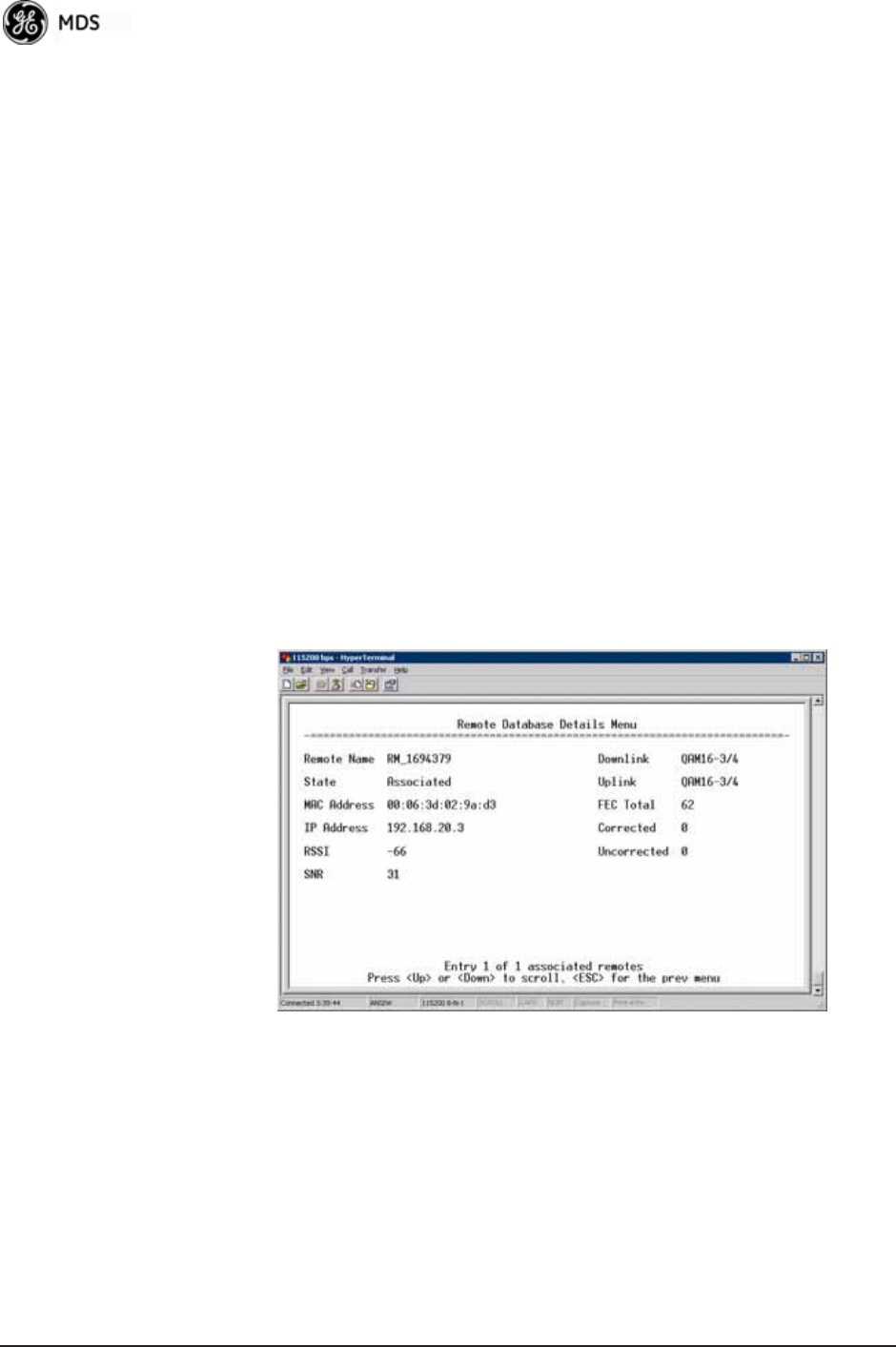
Radio Details—This selection presents a screen (
Figure 3-98)
showing key operating details of the transceiver.
• Channel Statistics—This selection presents a screen
(
Figure 3-99) that shows signal quality on a channel-by-channel
basis. Readings are expressed in RSSI dBm and Signal-to-Noise
Ratio (SNR) dB, respectively.
Invisible place holder
Figure 3-98. Radio Details Menu
• RSSI—Shows received signal strength indication (RSSI) in
dBm.
• SNR—Shows signal-to-noise ratio (SNR) in dB.
• TX Frequency Offset—Shows the RF carrier shift of the Remote’s
transmitter, measured in Hertz (Hz). The transmitted frequency
is continually reviewed and adjusted to agree with what the AP
expects to see. This optimization results in more efficient oper-
ation, corrects for doppler shift, and results in higher throughput
between AP and Remote stations.