
Reference Manual


8 Mercury Reference Manual 05-4446A01, Rev. E
The internal WiFi module has FCC modular approval and may only be
operated by connecting one of the GE MDS approved antennas (see
802.11 WiFi Module Specifications below) to the reverse-SMA con-
nector on the radio’s front panel. Only these antennas may be used. The
WiFi module can operate as an 802.11 Access Point or Infrastructure
Station, according to user configuration. The operational mode (
AP, Infra-
structure RM) and frequency can be configured through the unit's user
interface.
Invisible place holder
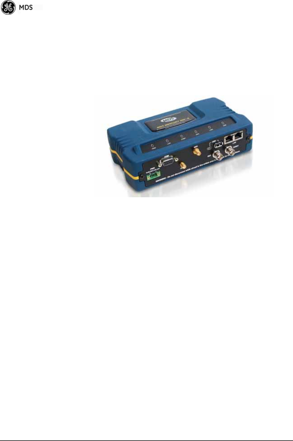
Figure 1-2. Mercury Remote with Option Set 1
(Note interface connector differences from Standard Remote)
802.11 WiFi Module Specifications
The specifications listed below are unique to Remotes with Option Set
1, which contain a 2.4 GHz WiFi module.
SPECIFICATIONS on
Page 178
contains a complete list of general Mercury Series specifica-
tions.
Protocol: IEEE 802.11b/g OFDM 6 to 54Mbps, CCK 1 to
11Mbps
Frequency Range: 2400 to 2500MHz
Maximum Transmit Power: 15 dBm
Permissible Antennas: MDS 97-4278A36
MDS 97-4278A34
MDS 97-4278A35
FCC: Part 15C
FCC ID: VRA-SG9011028
WiFi Antenna Connector: Female Reverse SMA
1.2.3 GE MDS P23 Protected Network (Redundant)
Configuration
For mission-critical applications, a Protected Network Station is also
offered. This unit incorporates two Access Points, two power supplies,
and a switchover logic board that automatically selects between Trans-
ceiver A and Transceiver B as the active radio.
Figure 1-3 shows the