
Reference Manual


05-4446A01, Rev. E Mercury Reference Manual 27
Invisible place holder
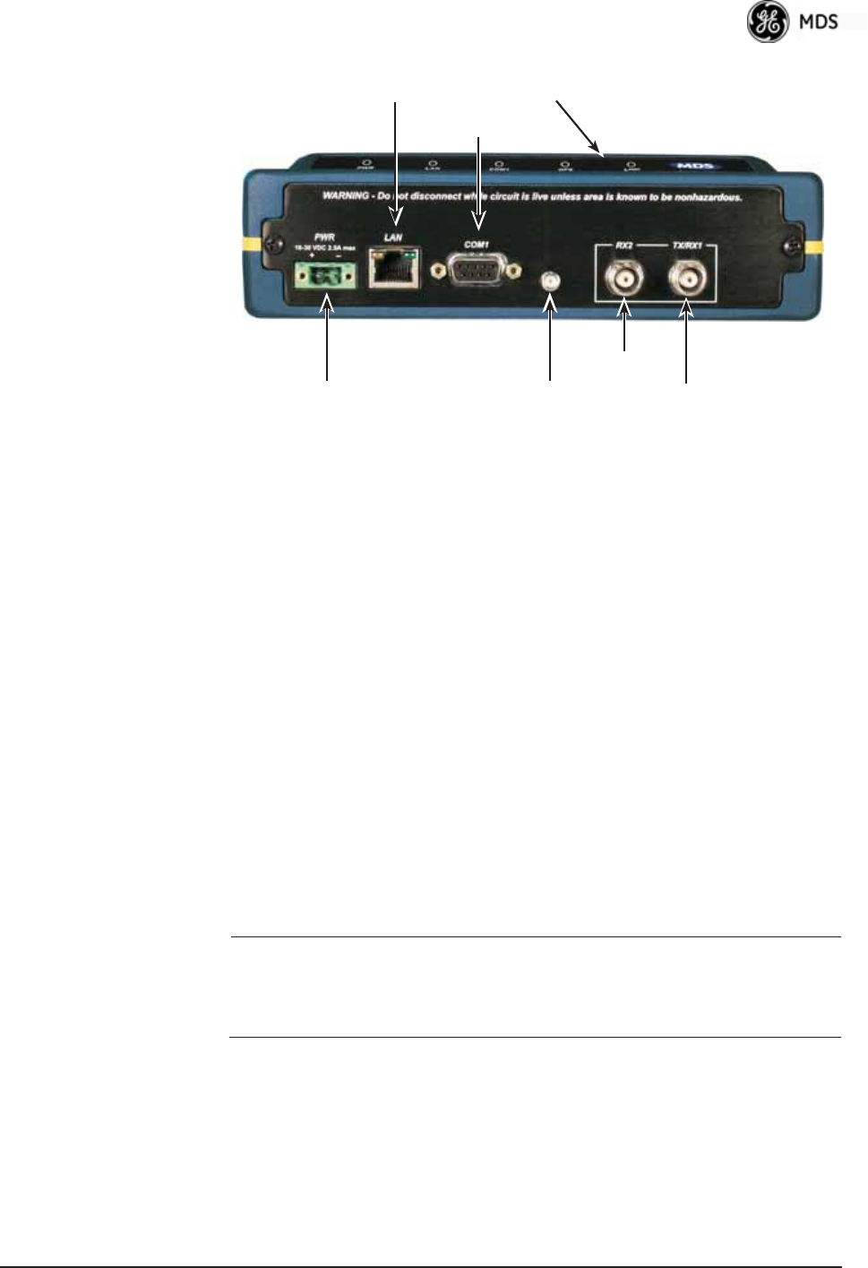
Figure 2-3. Transceiver Interface Connectors
(Standard unit shown; See Figure 2-4 on Page 28 for Option Set 1 unit)
• LED INDICATOR PANEL—Displays the basic operating status of
the transceiver. See section
2.7 on Page 29 for detailed informa-
tion.
•
COM1 SERIAL PORT— DB-9 connector used for management
of the transceiver with a connected PC.
INTRODUCTION on
Page 33 provides complete connection details.
•
LAN PORT—Connection point for Ethernet Local Area Net-
work. The connector has integrated LEDs to indicate signal
activity as follows: A steady green LED indicates that a link has
been achieved; a flashing green LED indicates data activity; and
a yellow LED indicates 100 Mbps operation.
•
PWR— DC power connection for the transceiver. Power source
must be 10 Vdc to 30 Vdc, negative ground, and capable of pro-
viding at least 25 watts.
•
GPS ANTENNA PORT— Coaxial connector (SMA-type) for
connection of a GPS receiving antenna. Provides 3.5 Vdc output
for compatibility with powered (active) GPS antennas. The GPS
receiving antenna’s gain must be 16 dBi or less.
NOTE: GPS functionality is required on all Access Points and
Remotes except when “Free Run” single-channel (non-frequency
hopping) operation is used, which might be possible in some
low-interference environments.
• RX2 ANTENNA PORT— Coaxial connector (TNC-type) for
attachment of a second receiving antenna used in space diver-
sity arrangements.
•
TX/RX1 ANTENNA PORT— Coaxial connector (TNC-type) for
attachment of the main station antenna (transmit and receive).
COM1
SERIAL PORT
LAN PORT
GPS ANTENNA
CONNECTION
RX2 ANTENNA
PORT
TX/RX1
ANTENNA PORT
DC POWER INPUT
(10—30 VDC, 2.5A)
LED INDICATOR
PANEL