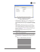
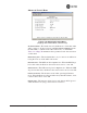
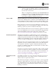
Invisible place holder Figure 3-37. Frequency Control Menu (Mercury 3650 model only) • Frequency (Mercury 3650 only)—Used to set/display the radio’s operating frequency. MDS 3650 radios do not employ frequency hopping, thus the entry here is a specific RF operating channel. The allowable entry range is 3650.000000 to 3700.000000 MHz. • Frequency Mode—The unit can operate on one selected frequency or frequency hop.
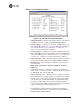
Table 3-1. Channel/Frequency Allocations (Continued) • Channel 1.75 MHz B/W 7 916.000000 8 917.800000 9 919.600000 10 921.400000 11 923.400000 12 925.200000 13 927.000000 3.5 MHz B/W RF Bandwidth—View/set the radio’s RF operating bandwidth. Radios are factory-configured for either 1.75 MHz or 3.5 MHz maximum bandwidth. Determine the factory configuration of a radio by viewing the “CONFIG” number on the label at the bottom of the radio. 1.
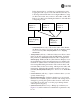
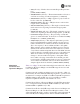
In the diagram below, one Remote is configured for static hopping and will only associate with AP1 because they are both using Offset 0. The hand-off configured Remote, using its AP Locations file, may connect to AP1, AP2, or AP3. The Remote does this by determining the Offset for each AP, then configuring its radio. AP 1 Pattern A Offset 0 AP 2 Pattern A Offset 1 RM Static Hopping Offset 0 • • • • • 05-4446A01, Rev.
• Hand-Off Mode Parameters Hardware Filter (900 MHz only)—This field provides a read-only indication of the maximum bandwidth of the radio. [1.75 MHz or 3.5 MHz] In a mobile or portable application, a Remote radio can move and associate with different APs depending on its location. The process by which the Remote ends the connection with one AP and begins a connection with another AP is called “hand-off.
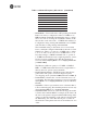
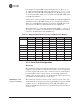
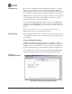
Advanced Control Menu Invisible place holder Figure 3-38. Advanced Control Menu (Hopping with Handoff Mode, Remote Only) AP Selection Mode—The method used by the Remote to determine what AP to connect to. It may be based on Signal, Distance and Bearing (from the AP's GPS coordinates in the AP locations file), or Connection. Table 3-2 on Page 70 summarizes these parameters and other selections on this menu.
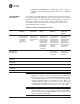
Advanced Configuration Menu Invisible place holder Figure 3-39. Advanced Configuration Menu • Adaptive Modulation—Enables automatic selection of modulation and FEC rate based on SNR. [enabled, disabled; enabled] • Protection Margin—A • • • • • number of decibels of SNR added to the minimum SNR required for a given modulation and FEC rate. See “Modulation Protection and Hysteresis Margins” on Page 73 for more information.
• • • • • • • • Modulation Protection and Hysteresis Margins (AP only)—Enables the Automatic Repeat Request function. [enable, disable; enabled] ARQ Window Size (AP only)—The maximum number of blocks to send before receiving an acknowledgement. [1—1024; 512] ARQ Block Size (AP only)—ARQ is applied to payload data in blocks of this size. [4—2040; 256] ARQ Block Lifetime (AP only)—ARQ blocks are valid for this length of time.
For example, the third SNR value in Column D is 11.4 dB (8.4 + 3 = 11.4 dB), and the third SNR value in Column E is 17.1 (11.1 + 3 + 3 = 17.1 dB). Note that with a Hysteresis Margin of 3 dB, there is an overlap of 3 between the Max SNR of one modulation and the Min SNR of the next higher modulation. In this case, if a link is operating with an SNR of 15 dB, then QPSK-3/4 modulation is used. The SNR must go above 17.1 dB before the link shifts up to 16QAM-1/2 modulation.
NOTE: To restore the COM1 port to support Management System services, connect a terminal to the port, select the proper baud rate (115,200 is default), and enter an escape sequence (+++) to reset it to the console mode. There is a configuration parameter for the console baud rate and another parameter for the serial data baud rate. These items can be different, so when switching out of data mode to console mode, the port might also change its baud rate. TCP vs.
UDP Multicast IP provides a mechanism to perform a limited broadcast to a specific group of devices. This is known as multicast addressing. Multicast addressing requires the use of a specific branch of IP addresses set apart by the Internet Assigned Numbers Authority (IANA) for this purpose. UDP multicast is generally used to transport polling protocols typically used in SCADA applications where multiple remote devices will receive and process the same poll message.
Figure 3-41. Serial Configuration Wizard • Begin Wizard—Tool for configuring serial ports using a step-by-step process. • View Current Settings—Displays all setable options. Varies depending on the selected IP protocol. Configuring for UDP Point-to-Multipoint Invisible place holder Figure 3-42. UDP Point-to-Multipoint Menu Use UDP point-to-multipoint to send a copy of the same packet to multiple destinations, such as in a polling protocol. • • 05-4446A01, Rev.
• • • • • • • • RX IP Port—Receive IP data from this source and pass it through to the connected serial device. The port number must be used by the application connecting to local TCP or UDP socket. [Any valid IP port; 30010] TX IP Address (used instead of Local IP Address when using UDP Point-to-Multipoint)— Configure with a valid Multicast address (224.0.0.0–239.255.255.255). IP packets received with a matching destination address are processed by this unit. [Any legal IP address; 0.0.0.
• • • • • • • • • • 05-4446A01, Rev. D Mode—UDP Point-to-Point. This is the type of IP port offered by the transceiver’s serial device server. [TCP, UDP; TCP] RX IP Port—Port number where data is received and passed through to the serial port. The application connecting to this transceiver must use this port number. [1—64,000; 30010] TX IP Address—Data received through the serial port is sent to this IP address. To reach multiple Remotes in the network, use UDP Point-to-Multipoint.
Configuring for TCP Mode Invisible place holder Figure 3-44. TCP Client Menu (Remote) • • • • • • • • • • 80 Status—Enable/Disable the serial data port. Mode—TCP Client. This is the type of IP port offered by the transceiver’s serial device server. [TCP, UDP; TCP] TX IP Address—The IP address to be used as a destination for data received through the serial port. [Any legal IP address; 0.0.0.
Invisible place holder Figure 3-45. TCP Server Menu (AP) • • • • • • • • Status—Enable/Disable the serial data port. Mode—TCP Server. This is the type of IP port offered by the transceiver’s serial device server. [TCP, UDP; TCP] RX IP Port—Receive IP data from this source and pass it through to the connected serial device. The application connecting to the local TCP or UDP socket must use this port number.
In TCP mode, the transceiver remains in a passive mode, offering a socket for connection. Once a request is received, data received at the serial port is sent through the IP socket and vice versa, until the connection is closed or the link is interrupted. In this mode, the transceiver behaves the same, whether it is an Access Point or a Remote. (See Figure 3-46 and Table 3-4) NOTE: The TCP session has a timeout of 10 minutes (600 seconds). If inactive for that time, the session is closed.
Invisible place holder 192.168.0.10 192.168.0.1 192.168.0.2 LA N COM 1 EIA-232 Terminal or Computer COM 2 PW R LIN K Access Point EIA-232 Remote RTU Figure 3-47. Point-to-Point Serial-to-Serial Application Diagram Table 3-5. Serial Port Application Configuration Transceiver Location Menu Item Setting Access Point (COM1) Status Enabled Data Baud Rate 9,600 (Example) SIFD 4 IP Protocol UDP Remote IP Address 192.168.0.
Invisible place holder 192.168.0.2 192.168.0.10 LA N 192.168.0.1 COM 1 EIA-232 COM 2 PW R LIN K Remote RTU 192.168.0.3 EIA-232 LA N COM 1 EIA-232 COM 2 PW R Terminal or Computer LIN K Access Point RTU Remote LA N COM 1 EIA-232 COM 2 PW R LIN K 192.168.0.4 Remote RTU Figure 3-48. Point-to-Multipoint Serial-to-Serial Application Diagram Invisible place holder Table 3-6.
Figure 3-49. Serial Port Configuration Access Point Figure 3-50. Radio Serial Port Configuration Remote Mixed Modes In this example, the TCP mode does not involve the Access Point. Thus, the transceiver in a single network can run in both modes at the same time. In other words, you can configure some Remotes for TCP mode and others (along with the Access Point) for UDP mode. In this configuration, the Host PC can use both data paths to reach the RTUs.
Operation and Data Flow • Communicate with RTU A by Telneting to Remote 1, port 30010. • Communicate with RTU B by Telneting to Remote 2, port 30010. • Communicate with RTUs C and D by sending and receiving data from the Access Point’s COM port. • All communication paths can be used simultaneously.
Table 3-7. Serial Port Application Configuration (Continued) Transceiver Location Menu Item Setting Send to Address IP address of the AP Send to Port 30010 Receive on Port 30010 Receive on Address 224.254.1.1 (The multicast IP address used for the AP’s Send To Address above) 3.
3.6.2 Menu Selections Connect a PC to the transceiver as described in STEP 3—CONNECT PC TO THE TRANSCEIVER section on Page 25, and access the embedded management system. Follow the steps below to proceed with Modbus/TCP configuration. 1. From the Serial Configuration Wizard opening screen (Figure 3-52 on Page 88), select A to begin the wizard. Invisible place holder Figure 3-52. Configuration Wizard Opening Screen 2.
Figure 3-54. Modbus/TCP Server Listening Port 4. On the next screen (Figure 3-55), press A to change the Modbus serial format, then press the space bar to toggle between the available formats (MODBUS/RTU or MODBUS/ASCII). Press B to enter the Modbus serial timeout value in milliseconds. Press N to continue the wizard. NOTE: The only difference between Modbus/RTU and Modbus/ASCII is the form of the framing sequence, error check pattern, and address interpretation. Figure 3-55.
5. When the next screen appears (Figure 3-56), press A to select the desired data baud rate and B to select the data byte format. Press N to continue. Figure 3-56. Select Data Baud Rate and Byte Format 6. The screen shown in Figure 3-57 appears next. Press A to select the Buffer Size of message packets, and B to select the Inter-Frame Delay. Press N to continue with the wizard. Invisible place holder Figure 3-57. Buffer Size and Inter-Frame Delay Values 7.
Invisible place holder Figure 3-58. Serial Port Status Screen 8. Review all settings on the summary screen shown in Figure 3-59. If all settings are correct, press X to confirm and exit the wizard. If not, select the letter of the item(s) you wish to change. Invisible place holder Figure 3-59. Serial Configuration Summary Screen This completes the menu selections for Modbus/TCP operation. 3.
Wireless Security—Controls how and when radios communicate with each other, as well as how data traffic is handled. RADIUS Configuration—Deals with IEEE 802.1x device authentication and authorization using a central server. Manage Certificates (Remote only)—Allows setting of certificate types, download paths, and TFTP parameters. Invisible place holder Figure 3-60. Security Configuration Menu Selecting any of the Security Configuration Menu items opens a submenu where you can view or change settings.
Invisible place holder Figure 3-61. Device Security Menu • Telnet Access—Controls Telnet access to the agement system. [enabled, disabled; enabled] • SSH Access—Controls access [enabled, disabled; enabled] • HTTP Mode—Controls • • • • 05-4446A01, Rev. D transceiver’s man- to the Secure Shell (SSH) server. access to the transceiver’s management system via the web server. [disabled, HTTP, HTTPS; HTTP] HTTP Auth Mode—Selects the mode used for authenticating a web user.
User Passwords Menu Invisible place holder Figure 3-62. User Passwords Menu To change the Administrator or Guest password, select the appropriate menu item (A or B). A flashing cursor appears to the right. From here, type the new password, which can be any alpha-numeric string up to 13 characters long. The change is asserted when you press the Return key. • Change Admin Password—Allows you to set a new [any alpha-numeric string up to 13 characters; admin] password.
Invisible place holder Figure 3-63. Wireless Security Menu • Device Auth Mode—View/set the device’s authentication method. [None, Local, IEEE 802.1X; None] • Data Encryption—Controls the over-the-air payload data’s AES-128 bit encryption. [enable, disable; disabled] • Encryption Phrase—View/set the phrase used to generate encryption keys when encrypting over-the-air payload.
Invisible place holder Figure 3-64. Approved Remotes Submenu • Add Remote—Enter the MAC address of Remote. [Any valid 6-digit hexadecimal MAC address; 00:00:00:00:00:00] • Delete Remote—Enter the MAC address of Remote. For security purposes, you should delete a stolen or deprovisioned radio from this list. • Add Associated Remotes—Add all currently associated remotes to the approved remote list. Alternatively, you can enter each Remote MAC manually.
Each Access Point and Remote radio must be identified/recognized by the device authentication server through the Common Name (Serial number) and IP address entries. NOTE: Consult your network administrator for assistance in configuration, or for help with other issues that may arise. To activate device authentication, select Device Auth Method and set as the active mode. The behavior of this setting differs depending on whether it is implemented on an Access Point or a Remote transceiver.
RADIUS Configuration Menu Invisible place holder Figure 3-65. Radius Configuration Menu • Auth Server Address—The IP address server. [any valid IP address; 0.0.0.0] • Auth Server Port—The [1812, 1645, 1812] • Auth Server Shared Secret—User of the authentication UDP Port of the authentication server. authentication and Device authentication require a common shared secret to complete an authentication transaction.
Invisible place holder Figure 3-66. Manage Certificates Menu Invisible place holder Figure 3-67. Manage Certificates Menu, TFTP Mode (Firmware version 3.0 Remotes) 05-4446A01, Rev.
Invisible place holder Figure 3-68. Manage Certificates Menu, USB Mode (Firmware version 3.0 Remotes) selection of methods for transferring files to and from the radio. On firmware version 3.0 radios, the options are TFTP and USB. • TFTP Host Address—(Telnet/Terminal only)—IP address of the computer on which the TFTP server resides. This same IP address is used in other screens/functions (reprogramming, logging, etc.). Changing it here also changes it for other screens/functions.
Invisible place holder Figure 3-69. Transfer Options Menu • TFTP Timeout—The time the client radio will wait for a response from the server before ending the transfer. • TFTP Block Size—The amount of data sent in each TFTP packet. 3.8 REDUNDANCY CONFIGURATION (AP ONLY) For operation in protected (redundant) mode, an AP must be in a Packaged P23 enclosure with a backup radio. See MDS publication 05-4161A01 for details. This manual is available under the Downloads tab at www.GEmds.com.
Invisible place holder Figure 3-70. Redundancy Configuration Menu (AP Only) • Redundancy Configuration—Enable/disable ver for AP. [enabled, disabled; disabled] • Network Event Triggers—This • • • • 102 redundancy switcho- selection opens a submenu (Figure 3-71 on Page 103) where you can set/view the trigger status for Network Events.
Network Event Triggers Menu Invisible place holder Figure 3-71. Network Events Triggers Menu • Network Interface Error—This setting determines whether or not a network interface error will cause redundancy switchover. [enabled, disabled; disabled] Radio Event Triggers Invisible place holder Figure 3-72. Radio Event Triggers • setting determines whether or not a switchover occurs when a lack of associated Remote units exceeds the time period set in Figure 3-75 on Page 105.
Hardware Event Triggers Invisible place holder Figure 3-73. Hardware Event Triggers • Init/Hardware Error—This setting determines whether or not an initialization or hardware error results in a redundancy switchover. [enabled, disabled; disabled] Redundancy Configuration Options Menu Use this menu (Figure 3-74) to set the thresholds for the Lack of Associated Remotes and Packet Receive Errors. Selecting either item opens a submenu where you can view or change settings.
• Packet Receive Errors Exceeded Threshold—This selection opens a submenu (Figure 3-76 on Page 105) where you can view or change the maximum allowable number of receive errors. Lack of Associated Remotes Exceeded Threshold Menu Invisible place holder Figure 3-75. Lack of Associated Remotes Exceeded Threshold Menu • Packet Receive Errors Exceeded Threshold Menu Lack of Remotes for—Select this item to change the time setting (in seconds) for a lack of associated Remotes.
3.9 GPS CONFIGURATION (REMOTE ONLY) This menu allows you to view or set important parameters for the built-in Global Positioning System (GPS) receiver in the Mercury Remote. Mercury 3650 Remote units do not have or require GPS functionality. Details about the NMEA sentences generated by the GE MDS Mercury can be found at http://www.nps.gov/gis/gps/NMEA_sentences.html. Invisible place holder Figure 3-77.
Invisible place holder Figure 3-78. GPS Streaming Configuration Menu • • • • • • • • 05-4446A01, Rev. D GGA Polling—Seconds between GGA string outputs, the satellite fix information. GLL Polling—Seconds between GLL string outputs, the latitude and longitude information. GSA Polling—Seconds between GSA string outputs, the overall satellite data. GSV Polling—Seconds between GSV string outputs, the detailed satellite data. RMC Polling—Seconds between RMC string outputs, the recommended minimum data.
3.10 DEVICE INFORMATION MENU Figure 3-79 shows the menu that displays basic administrative data on the unit to which you are connected. It also provides access to user-specific parameters such as date/time settings and device names. Figure 3-79. Device Information Menu • • • • Model (Display only) Serial Number (Display only) time since boot-up. Date—Current date being used for the transceiver logs. User-setable.
• • UTC Time Offset—Set/view the number of hours difference between your local clock time and Universal Coordinated Time. Offsets for U.S. times zones are shown in the chart below. Time Zone (U.S.) UTC Offset (Hours) PST -8 MST -7 CST -6 EST -5 Device Names—Fields used at user’s discretion for general administrative purposes. The Device Name field is shown on all menu screen headings.
important troubleshooting tool, or for evaluating changes made to the network configuration or equipment. Invisible place holder Figure 3-81. Performance Information Menu • • • • • • • 110 Event Log—Access this menu for managing the unit’s operational activities log. (See Figure 3-84 on Page 112 for details.) Packet Statistics—Multiple radio and network operating statistics. (See Figure 3-86 on Page 114 for details.
Invisible place holder Figure 3-82. Performance Trend Screen Invisible place holder Figure 3-83. Bridge Status Menu 05-4446A01, Rev.
Event Log Menu Invisible place holder Figure 3-84. Event Log Menu • Current Alarms—Shows active alarms (if any) reported by the transceiver. • • • • • • • 112 View Event Log—Displays a log of radio events arranged by event number, date, and time. (Example shown in Figure 3-85 on Page 113). Clear Event Log—Erases all previously logged events. Send Event Log—Sends the event log to the server. You must answer the challenge question Send File? y/n before the request proceeds.
View Event Log Menu Invisible place holder Figure 3-85. View Event Log Menu The transceiver’s microprocessor monitors many operational parameters and logs them. Events are classified into four levels of importance, which are described in Table 3-8. Some of these events result from a condition that prevents normal operation of the unit. These are “critical” events that cause the unit to enter an “alarmed” state and the PWR LED to blink until the condition is corrected.
Invisible place holder Figure 3-86. Packet Statistics Menu • • • • • • • • • 114 Packets Received—Data packets received by this unit. Packets Sent—Data packets sent by this unit. Bytes Received—Data bytes received by this unit. Bytes Sent—Data bytes sent by this unit. Packets Dropped—To-be-transmitted packets dropped because of a lack of buffers in the outbound queue. Receive Errors—Packets that do not pass CRC.
GPS Status Menu Invisible place holder Figure 3-87. GPS Status Menu • GPS Serial Number—The serial number of the GPS unit in the • GPS Firmware Version—The • Satellite Fix Status—Indicates radio. firmware version running on the GPS chip. • • • • • 05-4446A01, Rev. D whether or not the unit has achieved signal lock with the minimum required number of GPS satellites. The transceiver requires a fix on five satellites to achieve Precise Positioning Service (PPS) and four to maintain PPS.
GPS Information Menu Invisible place holder Figure 3-88. GPS Information Menu Wireless Network Status Menu The Wireless Network Status screen provides information on a key operating process of the transceiver—the association of the Remote with the Access Point. The following is a description of how this process takes place and is monitored by the menu system.
Invisible place holder Figure 3-89. Wireless Network Status Menu (AP) Invisible place holder Figure 3-90. Wireless Network Status Menu (Remote) • Device Status—Displays the overall transceiver. [Operational, Alarmed] • Associated Remotes operating condition of the (AP Only)—Shows the number of Remote transceivers currently associated with the AP.
• • • • • (Remote Only)—Displays the current state of the wireless network communication as follows: Scanning, Ranging, Connecting, Authenticating, Associated, or Alarmed. A complete explanation of these operating states is provided in Table 4-3 on Page 150. Current AP Eth Address—Displays the Ethernet MAC address of the current AP. Current AP IP Address—Shows the IP address of the current AP. Current AP Name—Displays the device name of the current AP.
Invisible place holder Figure 3-93. Remote Database Details Menu (AP) Internal Radio Status Menu (Remote Only) Invisible place holder Figure 3-94. Internal Radio Status (Remote Only) 05-4446A01, Rev.
Invisible place holder Figure 3-95. Internal Status Menu (Remote in Static Hopping mode) Invisible place holder Figure 3-96. Internal Radio Status Menu (Remote in Hopping with Handoffs Mode) NOTE: In the menu above, the items in the right hand column are displayed on Remotes only, when they are in Hopping with Handoffs mode. This allows viewing of the settings the Remote is using to connect to each AP in the AP Locations File. See Frequency Control Menu on Page 65 for explanations of these items.
• • • • • • Transmit Power—Shows the RF power output from the transmitter. The AP changes the transmit power of the Remote to match the desired receive power at the APs receiver. This provides end-to-end power control. Average RSSI—Shows average received signal strength indication (RSSI) of incoming RF signals, displayed in dBm. Average SNR—Shows average signal-to-noise-ratio (SNR) of received signals, displayed in dB. This is a measurement of the quality of the incoming signal.
• RX Frequency Offset—This is a measurement of how far in frequency the Remote’s receiver has shifted (in Hz) to accommodate the incoming signal from the AP. • Total FEC Count—This parameter shows the total number of Forward Error Correction (FEC) blocks handled by the radio. • Corrected FEC Count—Displays the number of errored blocks corrected with FEC by the radio. • Uncorrected FEC Count—Shows the number of errored blocks that can’t be corrected with FEC by the radio.
Invisible place holder Figure 3-99. Maintenance/Tools Menu (AP) Invisible place holder Figure 3-100. Maintenance/Tools Menu (Remote) (Some versions may show a • • • • • 05-4446A01, Rev. D Scheduled Reboot option, described below) Reprogramming—Managing and selecting the unit’s operating system firmware resources. (See “Reprogramming Menu” on Page 125) Configuration Scripts—Saving and importing data files containing unit operating parameters/settings.
• Radio Test—A diagnostic tool for testing RF operation. (See “Radio Test Menu” on Page 137) • Firmware Versions—Shows the firmware code versions stored in the radio and indicates which one is the active image. (See Figure 3-101 on Page 124.) • Auto Firmware Upgrade—Brings up a submenu where you can perform tasks related to loading new firmware. (See “ Auto Firmware Upgrade Menu (AP Only)” on Page 137.
Reprogramming Menu The factory sometimes offers upgrades to the transceiver firmware. Loading new firmware into the unit will not alter any privileges provided by Authorization Keys and does not require you to take the transceiver off-line until you want to operate the unit with the newly installed firmware image. Firmware images are available free-of-charge at: www.GEmds.com/Resources/TechnicalSupport/ NOTE: Always read the release notes for downloaded firmware.
Invisible place holder Figure 3-104. Reprogramming Menu (Firmware 3.0 Remote Only, TFTP Mode) Invisible place holder Figure 3-105. Reprogramming Menu (Firmware 3.0 Remote Only, USB Mode) selection of methods for transferring files to and from the radio. On firmware version 3.0 radios, the options are TFTP and USB. • TFTP Host Address—IP address of the host computer from which to get the file. [Any valid IP address] This same IP address is used in other screens/functions (reprogramming, logging, etc.).
• • • • • • Retrieve File—Initiates the file transfer from the TFTP server. The new file is placed into inactive firmware image. [Y, N] Image Verify—Initiate the verification of the integrity of firmware file held in unit. Image Copy—Initiate the copying of the active firmware into the inactive image. Reboot Device—Initiates rebooting of the transceiver. This will interrupt data traffic through this unit, and the network if performed on an Access Point.
3.12.1 Installing Firmware via TFTP Firmware images are available free-of-charge at: www.GEmds.com/Resources/TechnicalSupport/. NOTE: You may not install AP firmware in Remote radios, or vice-versa. This was only possible for early (pre-version 2.1.0) firmware. To install firmware by TFTP, you need: • A PC with a TFTP server running • The IP address of the PC running the TFTP server • A valid firmware file The IP address of the radio can be found under the Management System’s Starting Information Screen.
Invisible place holder REMOTE PC W/FIRMWARE FILES TFTP SERVER HUB/LAN/WAN/MAN TCP/IP ETHERNET PORT TRANSCEIVER IP ADDRESS: 172.0.0.B LE AB STRA C IGHT-THRU IP ADDRESS: 172.0.0.A LAN PORT LOCAL WINDOWS PC COM1, 2, ETC. (DTE) L NA MI AM R R TE OG PR 9-PIN SERIAL IP ADDRESS: w.x.y.z LE CAB COM1 PORT (DCE) INITIATE UPLOAD FROM HERE Figure 3-108.
5. Download the firmware file from the TFTP server into the transceiver. (Main Menu>>Maintenance Menu>>Reprogramming Menu>>Retrieve File) Status messages on the transfer are posted on the Management System screen. NOTE: The new firmware image file that replaces the “Inactive Image” file is automatically verified. 6. Reboot the transceiver. Main Menu>>Maintenance Menu>>Reprogramming Menu>>Reboot Device 7. Test the transceiver for normal operation.
• To save “known-good” configuration files from your radios. These can be used for later restoration if a configuration problem occurs, and it is unclear what parameter is causing the issue. • To facilitate the rapid configuration of a large number of radios. • To provide troubleshooting information when you contact the factory for technical support. A technician can often spot potential problems by reviewing a configuration file.
Invisible place holder Figure 3-110. Configuration Scripts Menu (Firmware 3.0 Remote Only, TFTP mode) Invisible place holder Figure 3-111. Configuration Scripts Menu (Firmware 3.0 Remote Only, USB mode) selection of methods for transferring files to and from the radio. On firmware version 3.0 radios, the options are TFTP and USB. • Config Filename—Name of file containing this unit’s configuration profile that will be transferred to the TFTP server.
NOTE: The filename field is used to identify the desired incoming file and as the name of the file exported to the TFTP server. Before exporting a unit’s configuration, name it in a way that reflects the radio’s services or other identification. • • • • • TFTP Host Address—IP address of the computer on which the TFTP server resides. [Any valid IP address] Transfer Options—A menu for configuring the TFTP transfer. Category—The category of parameters to send or receive.
Table 3-10. Common User-Alterable Parameters (Continued) Field Device Name Comment Range Should reflect a specific device. Any 20-character alphanumeric string This information will appear in Management System headings. Location Editing Rules Used only as reference for network administration. Any 40-character alphanumeric string • Only include parameters you want to change from the default value. • Change only the parameter values. • Capitalization counts in some field parameters.
• Ping—Send Ping packets to address shown on screen. This screen is replaced with a detailed report of Ping activity (see example in Figure 3-113). Press any key after viewing the results to return to this menu. Invisible place holder Figure 3-113. Ping Results Screen Authorization Codes Invisible place holder Figure 3-114. Authorization Codes Menu • entering an Authorization Key into the transceiver’s non-volatile memory. • Authorized Features—List of the transceiver’s authorized features.
Reset to Factory Defaults Use the Reset to Factory Defaults selection on the Maintenance/Tools Menu to return all configurable settings to those set at the factory prior to shipping. Use this selection with caution, as you will lose any custom settings you have established for your transceiver, and will need to re-enter them using the menu system.
3.12.2 Auto Firmware Upgrade Menu (AP Only) Invisible place holder Figure 3-116.Auto Firmware Upgrade Menu • Firmware Upgrade—Causes all of the Remotes associated to this AP to read the AP’s specified (by Firmware for Upgrade) firmware version (active or inactive), and download it via TFTP to the inactive image if the Remote does not already have that firmware version. • Firmware Autoboot—Boot connected remotes to Firmware for Upgrade (see below).
Invisible place holder Figure 3-117. Radio Test Menu NOTE : Using Test Mode disrupts traffic through the radio. If the unit is an Access Point, it will disrupt traffic through the entire network. The Test Mode function is automatically limited to 10 minutes. Only use Test Mode for brief measurements. • Radio Mode—Sets/displays the radio’s operating mode. To change the setting, press A on the PC’s keyboard and press the Spacebar to toggle between the two settings.
Spectrum Analyzer Menu (Remote Only) Using this menu, you can enable or disable the remote’s spectrum analyzer mode (Figure 3-118 on Page 139). When enabled, the remote displays through the terminal a spectrum analyzer view of its transmit power and frequency (Figure 3-119 on Page 139). Figure 3-118. Spectrum Analyzer Menu Figure 3-119. Spectrum Analyzer Display 3.13 PERFORMANCE OPTIMIZATION After checking basic radio operation, you can optimize the network’s performance.
There are two major areas for possible improvement—the radio and the data network. These sections provide a variety of items to check in both categories, and in many cases, ways to improve performance. NOTE: Antennas are one of the most important portions of the wireless system. A properly installed antenna with an unobstructed path to associated stations is the optimal configuration, and should be among the first items checked when searching for performance gains.
Table 3-11. Recommended Settings for Common Scenarios For Fixed Locations, where best combination of range and throughput is desired. Remote User discretion User discretion Transmit Power (AP)/ Max Transmit Power (RM) 30 (3650 model: 23) 30 (3650 model: 23) dBm In most cases, power can be set to this level and left alone. Setting it lower helps control cell overlap. Receive Power -70 N/A dBm Sets AP receiver for medium gain. Typical range: -60, -80 dBm.