
User's Manual


MDSSDM4
QuickStartGuide(x790Mode)
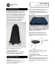
The MDS SDM4 transceiver (Figure 1) is a software-
configurable, industrial Master Station solution for use
in wireless telemetry applications. In this guide, the
term SD is used for information common to all models
of the radio. This radio module is designed for use
with a card cage and backplane similar to that shown
in Figure 3, and to be used with a variety of data
control equipment such as remote terminal units
(RTUs), programmable logic controllers (PLCs), flow
computers, and similar devices. Data interface
connections may be made by both serial (RS-
232/485) and limited Ethernet protocols.
Invisipbllhaeoc led er
Figure 1. MDS SDM4 Data Transceiver
1.1 About This Guide
This guide covers SDM4 transceivers operating in
x710-Compatible Mode. All GE MDS manuals are
available free of charge at www.gemds.com.
Invisipbllhaeoc led er
There are three main requirements for installing the
transceiver:
• Adequate and stable primary power
• An efficient and properly installed antenna system
• Correct interface connections between the
transceiver and the data device.
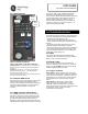
Figure 2 shows a chassis with card cage and
backplane that this module would be typically installed
in. The backplane provides the 24V power
connection to this unit and provides the customer data
interfaces through the card edge connector on the
rear of the SDM4.
Figure 2: Typical Orbit MPRS Master Station
Chassis. The SDM4 modules may be installed in any
free peripheral slot of this chassis.
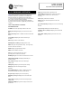
Figure 3 shows a typical installation of the radio.
NOTE: Retrofit Kits are available to simplify
installation at former MDS x710 digital and analog
sites. Consult the Reference Manual for ordering
details.
Figure 3: Typical Master Station Chassis with
SDM4 radio card installed. NOTE: Chassis has
antenna connection in rear, with power and data
connections in the front.
2.1 Installation Steps
1. Install the transceiver into chassis as shown in
Figure 2.
NOTE: To prevent damage to the SDM4 radio, wear a
wrist strap to prevent ESD discharge to the card edge
connector. Also, dress all cables as required to
prevent moisture from running along the cables and
into the radio.
1.0 INTRODUCTION
2.0 INSTALLATION