
User's Manual

2 MDS Master Station Setup Guide 05-6398A01, Rev. D
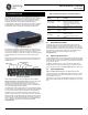
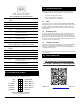
Figure 3: Application Example
2.0 INSTALLATION
Refer to the figures which follow for these steps, as required:
1. Mount the unit. The unit may be rack-mounted (2U high) in a
19-inch rack cabinet or may be placed on any sturdy tabletop or
other flat surface. The installation site should be free of excessive
dust, and should have adequate ventilation. The chassis should be
positioned so that all interface cabling will reach the required con-
nectors.
When rack mounting, the rack ears can be installed in one of three
positions to allow flexibility in the mounted depth of the chassis. The
unit should be mounted so as to maximize airflow around the rear
heat sink.
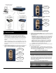
2. Connect Antenna Feed-lines. All coaxial antenna connections are
made to the Type-N connectors on the rear of the unit. Figure 4,
Figure 5, and Figure 6 illustrate the antenna options available;
Figure 4: Internal Duplexer, Triple N connectors
Figure 5: Internal Duplexer (or internal T/R switch),
Single N connector
Figure 6: External duplexer or dual antennas
(TX and RX ports pass directly through)
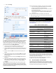
3. Install the Data Interface Cabling. Interface connections are made
to the front of the Platform Manager module. Typical connections for
most sites include:
• Serial Data—Attach data equipment to the front panel COM1 or
COM2 port. By default, the COM2 port is set for management
and must be configured for data before connecting data equip-
ment. The unit is hardwired as a DCE device, thus a
straight-through Ethernet cable may be used in most cases
(DB9-F to RJ-45 connector, GE MDS part no. 73-2434A12).
• Ethernet LAN—Attach data equipment to the ETH1 and/or
ETH2 port. The auto-sensing MDIX feature allows either a
straight-through or crossover cable to be used.
Where applicable in the steps that follow, secure all cable connections
with the locking screws provided.
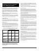
4. Connect Primary Power—The Master Station is powered using
one or two power supply modules that work in tandem. The modules
may be AC, DC, or a combination of both. The following tables list
each type and key operating parameters.
Table 2: AC Power Supply Module
Module Input Power Current Rating
6755 100-264 VAC, 50/60 Hz 120W Max.
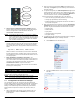
All DC power supply modules have chassis isolated inputs and a
diode bridge for floating ground, positive ground, or negative ground
installations. These modules include a keyed power connector with
screw-terminals. Strip the wire leads to 6mm (1/4 inch) and insert
them into the wire ports provided. Be sure to observe the polarity
shown below. Tighten the binding screws securely and insert the
connector into the module.
Table 3: DC Power Supply Modules
Module Input Power Current Rating
6843 +/- 12-30 VDC 10 A Max
6844 +/- 36-75 VDC 3.5 A Max
6845 +/- 75-140 VDC 2 A Max
Connector 2:
RX Output to external
notch filter
Connector 1:
TX/RX Antenna Port
Connector 3:
RX Input from external
notch filter
Connector 1:
TX/RX Antenna Port
Knockout covers
installed on unused
ports
Connector 1:
TX Output Port
Connector 2:
RX Input Port