
Operating Instructions


TXE
CONNECTION
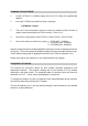
Connection to the ST600 transmitter is via PL1, PL2 and PL3 which plug directly into
the user's own equipment. The location of these connectors is shown in Figure 1 and
detailed in the following tables. (The unit is fitted with a 10 pin connector when parallel
frequency select facility is provided).
PIN NAME FUNCTION REMARKS
1 0V 0 volts common ground
2 RF O/P RF output 50 ohms output
3 0V 0 volts common ground
Connector PL1 pin detail
PIN NAME FUNCTION REMARKS
1 +VIN positive supply +6.0V to +15.0V
2 0V 0 volts common ground
Connector PL2 pin detail
PL1
PIN
NAME FUNCTION REMARKS
1 0V 0 volts common ground
2 transmit enable o/c = transmitter disabled
LOW <+0.5V = transmitter enabled
1k nom. internal pull-up to +Vin
3 DIGITAL I/P data input 0/+3V to 0/+12V, DC-coupled
4 ANALOGUE I/P data input > 50 mV p-p, AC-coupled
5 +5V
OUT
+ 5 volt supply output 50mA maximum current drain
6 RS232 I/P serial programming
i/p
RS232 level programming input
Note: Inverted TTL data can also be used.
If not used, leave not connected, or
connect to 0/V
7 0V 0 volts common ground
8 RB1
parallel frequency
select
internal pull-up to +5V, active low
9 RB2
10 RB3
Connector PL3 pin detail