
Operating Instructions


Parallel channel selection
To enable parallel channel selection mode press the F4 (Parallel channel mode)
function key, The screen then displays ‘parallel channel selected’.
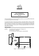
Three inputs RB1, RB3 and RB3 applied via PL3 to pin 8, pin 9 and pin 10 respectively,
select the operating channel as shown in the following table.
CHANNEL SELECTION
PIN 10 PIN 9 PIN 8 CHANNEL
LOW LOW LOW 7
LOW LOW HIGH 6
LOW HIGH LOW 5
LOW HIGH HIGH 4
HIGH LOW LOW 3
HIGH LOW HIGH 2
HIGH HIGH LOW 1
HIGH HIGH HIGH 0
The logic levels are : LOW < 0.8V
HIGH > 2V or floating
Programming random channels
Random channels between 0 and 15 can be entered using the Up 8 and Down 9 arrow
keys and then entering the required operating frequency. The entered value must be
an integer multiple of comparison frequency otherwise an ‘invalid’ message is
displayed.
Programming sequential channels
To generate a new frequency table the following parameter values must be entered:
- start frequency
- the table step as a multiple of comparison frequency.
The maximum frequency is calculated from the start table frequency and the table step..
Therefore if the calculation exceeds the maximum frequency then this parameter will
be increased automatically.
When the frequency table has been generated the user then selects F6 to program the
unit, assuming the unit has been read before.
The function key F2 can be used to copy the contents of channel 16-31 to channel 0 -
15 to ease sequential programming.