
Operating Instructions


Programming from customer equipment
In the event of a customer wishing to program the ST600 transmitter from his own
equipment then the following data sequence must be used allowing 5ms between the
characters in the data stream:
1200 baud, RS232 levels, 1 start bit - 8 bit data - no parity - 1 stop bit
40 (decimal 64) synchronising code
7 bit channel 0 - 127 (bit 7 = 0)
95 (decimal 149) confirmation byte
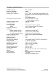
RANGE INFORMATION
The following table gives an indication of the typical ranges to be expected between a
transmitter and receiver that have simple end-fed dipole antennas.
The following assumptions have been made in the calculations:
line-of-sight between antennas
0dB gain for the transmitter and receiver antennas
0dB loss for connectors and cables between the antenna and the radio
connector
20dB fade and environmental margin
-100dBm received signal strength, allowing for digital and analogue signals
Range versus TX power
Frequency (MHz) Power (mW) Power (dBm) Range
(km)
Miles
600 1mW 0 0.4 0.3
600 10mW 10 1.3 0.8
600 25mW 14 2.0 1.2
600 100mW 20 4.0 2.5
600 500mW 27 8.9 5.5