
Manual


6
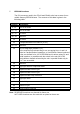
5 EEPROM locations
The PIC processor used in the STn00 and SRn00 units has an area of non-
volatile memory EEPROM area. The contents of this data is given in the
following table:
Location Description
0 - 15 RX/TX div msbs
16 - 31 RX/TX div lsbs
32 - 47 not used
48 - 49 reserved
50 not used
51 is sequential table limit channel (0-111)
52 - 53 reserved
54 SETUP flags byte (default is FF).
At the moment only relevant flag is one occupying bit no 1 and it is
Serial or Parallel mode of operation. In Serial Mode Channel selected
is the one defined in loc. 63 of EEPROM and is written using PC and
serial interface. In parallel mode the switch in the unit (D0 to D2
lines) defines channel selected by the unit. In parallel mode only ch.
0 to 7 are accessible.
55 reserved
56 high byte offset for sequential table
57 sequential table start hi byte
58 sequential table start lo byte
59 sequential table step increment
60 high byte offset
61 Rvalue hi byte
62 Rvalue lo byte
63 serial channel selected
Note: RESERVED locations are planned for future use
NOT USED locations are not used with no plans for future use.