
Operating Instruction


Simplified Operating Instruction, 340M OB Telemetry, 608-614MHz
GE Medical Systems Information Technologies 4/9/01
Page 2 of 8
Antenna jack (RA female BNC) top center
Connect to ¼ wave stainless whip
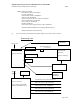
342 Transmitter:
Front Panel:
Ultrasound Transducer jack left
ECG Transducer jack center
UA transducer jack right
Rear Panel:
Headphone jack far left
Remote mark transducer jack left
Power switch right
Antenna jack (BNC) far right
Connect to ¼ wave helical wound ant.
Bottom Panel:
Battery access door
Radiation Hardened Simulator (for use at ITS, Boxborough):
This is an aluminum die-cast box containing (2) Alkaline ‘D’ cells providing power, and active circuitry
providing signal to the 5700 Ultrasound Transducers and UA Transducer plug.
Top:
Power switch:
Must be in the ‘ON’ position to obtain simulated transducer signal. Turn ‘OFF’ when not
needed to conserve battery.
UA Ref pushbutton:
Forces UA simulated signal to a baseline level for physiologic signal drift testing. Not
used for RF testing.
Adjustment Potentiometer:
Allows UA simulated signal to be offset from baseline level by adjustable amount. Not
used for RF testing.