
Step-by-step Instructions


Revision A Model 340 Telemetry System 4-3
2006899-001
Setup Procedures: Connecting the Receiver and Monitor
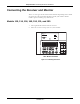
3. Insert the receiver antenna (longer of the two antennas) into the rear
panel
Antenna connector ; rotate the attachment collar in a
clockwise direction until snug.
127(A Remote Antenna Bracket, cat. no. (REF) 1441AAO, is
available for attaching the antenna when the receiver will be
enclosed in a cart or cabinet. Refer to the Installation
Instructions, part no. (REF) 14153AA, included with the
bracket; or contact your Biomedical Engineering Department
for assistance. To attach the antenna to the BNC connector
on the bracket, rotate the antenna attachment collar in a
clockwise direction until snug.
Figure 4-2. Attaching the Receiver Antenna
4. Connect the appropriate ultrasound, ECG, and uterine activity
interconnect cables to the corresponding
Ultrasound, ECG, and UA
connectors on the receiver rear panel.
Figure 4-3. Attaching the Receiver Interconnect Cables
ANTENNA
OUTPUTS TO MONITOR
CONNECT TO
COROMETRICS
MONITORS ONLY
ULTRASOUND
ECG
UA
!
WARNING: TO REDUCE FIRE HAZARD
REPLACE FUSE AS MARKED.
CAUTION
!
120Vac
~
120V ~ 50-60HZ 30W
0.25A SLOW BLOW