
Step-by-step Instructions


Revision A Model 340 Telemetry System 4-5
2006899-001
Setup Procedures: Connecting the Receiver and Monitor
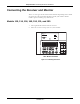
120 and 170 Series
,03257$17
120 SERIES COMMUNICATIONS OPTION—A 120
Series Monitor requires a Communications Board in
order to interface to a Model 340 Telemetry System. If
your monitor does not have this option, an upgrade kit is
available as cat. no. (REF) 1559BAO. Contact your
Service Representative for more information.
1. Turn off both the monitor and the receiver.
2. Place the receiver on top of, or near, the monitor.
3. Insert the receiver antenna (longer of the two antennas) into the rear
panel
Antenna connector ; rotate the attachment collar in a
clockwise direction until snug.
127(A Remote Antenna Bracket, cat. no. (REF) 1441AAO, is
available for attaching the antenna when the receiver will be
enclosed in a cart or cabinet. Refer to the Installation
Instructions, part no. (REF) 14153AA, included with the
bracket; or contact your Biomedical Engineering Department
for assistance. To attach the antenna to the BNC connector
on the bracket, rotate the antenna attachment collar in a
clockwise direction until snug.
Figure 4-6. Attaching the Receiver Antenna
ANTENNA
OUTPUTS TO MONITOR
CONNECT TO
COROMETRICS
MONITORS ONLY
ULTRASOUND
ECG
UA
!
WARNING: TO REDUCE FIRE HAZARD
REPLACE FUSE AS MARKED.
CAUTION
!
120Vac
~
120V ~ 50-60HZ 30W
0.25A SLOW BLOW