
GE Altitude Series Service Manual


REFERENCE INFORMATION
PAGE 47
ENGLISH
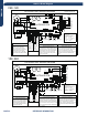
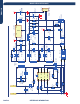
Indoor Board Diagram
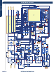
REFERENCE INFORMATION
PAGE 59
ENGLISH
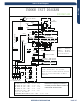
Indoor Board Diagram
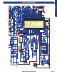
Indoor AW09ES2VHA AW12ES2VHA AW18ES2VHA AW24ES2
R:Red
W:White
Y:Yellow
Y/G:Yellow/Green
B:Black
BR:Brown
BL:Blue
PIPING TEMP.SENSOR
AMBIENT TEMP.SENSOR
SWITCH
EMERGENCY
INDOOR UNIT DIAGRAM
0010561514H
Notes:
1.The dotted parts are optional.
2.The two pins of CN51 should be shorted,
when the second channel(RC) of SW2 is
selected.
UP-DOWN
STEPMOTOR
M
FUSE1
SW1
CN7
T3.15A/250VAC
TO OUTDOOR UNIT
1
(N)
(C)
3
(L)
2
W
B
Y/G
GND
CN14
CN6
CN10
LEFT STEPMOTOR
CN11
CN5'
R
C0N1
BL
(L)
CN21
N
S
CN51
CN9
CN52
CN23
CN34
WIFI
CN2
WIRED CONTROLLER
FRESH AIR
RIGHT STEPMOTOR
ROOM CARD
CN5
DC FAN MOTOR
C0N2
C0N3
R
W
ION
GENERATOR
Y/G
CN11'
DISPLAY BOARD
SW2
1
2
3 4
ON
POWER SUPPLY
BR BL
Y/G
CN1
(CN5'')
Model selection:
09K model-23 code - SW2 - 3 off 4 off
12K model-26 code - SW2 - 3 off 4 on
18K model-33 code - SW2 - 3 on 4 off
24K model-35 code - SW2 - 3 on 4 on
Except for this model:
AS18ND1HRA/AW18LC2VHB-23 code - SW2 - 3 off 4 off
Notes:Before replacing the board,It is
necessary to ensure that the machine is
matched with the board code.
15K model-33 code - SW2 - 3 on 4 off