
GE Altitude Series Service Manual


INDOOR UNIT CONTROLS & COMPONENTS
PAGE 18
ENGLISH
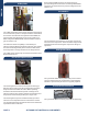
Terminal Block
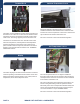
Display
The indoor unit terminal block receives electrical power from
the outdoor unit. There are 4 connections for electrical wires.
Terminals 1 and 2 are connected to terminals 1 and 2 of the
outdoor unit. This wiring supplies power to the indoor unit.
Terminal 3 is a communication wire. The indoor unit sends
indoor air temperature, coil temperature and temperature
setpoint information to the outdoor unit on this wire. If a
splice or break in this wire is present, the indoor unit will not
be able to communicate with the outdoor unit. The ERROR
CODE will be code E7.
The indoor display has an infrared communication circuit that
receives operating commands from the remote control. This
display will indicate operating modes, error codes, indoor air
temperature, timer status and power status.
Ambient Temperature Sensor
The Room Ambient Temperature Sensor is a negative
coecient thermistor that will decrease in resistance with
increases in room air temperature. The sensor is located on a
clip mounted to the surface of the indoor coil.
The sensor connects to the control board at Plug CN-6.
Coil Temperature Sensor
The Coil Temperature Sensor is a negative coecient
thermistor that will decrease in resistance with increases in
coil temperature. The sensor is located in a socket soldered
to the surface of the indoor coil.
This sensor will monitor the temperature of the indoor coil
in both cooling and heating modes of operation. Should
abnormally cold or hot coil temperature be detected by this
sensor, the system will take functional corrective steps to
correct the condition or report an ERROR CODE.
The sensor connects to the control board at Plug CN-6.