Installation Instructions Ductless Multi Zone with Highwall Indoor Units READ CAREFULLY. KEEP THESE INSTRUCTIONS. 31-5000560 Rev.
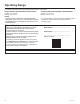
Operating Range The following information lists the operating range specific to each model. ASH218JCDDA1/ ASH324JCDDA1/ ASH436JCDDA1 Cooling: 14°F to115°F Heating: -4°F to 75°F NOTES: • The unit will stop running when outdoor temperature drops below -22°F (-30°C). The unit will resume operation automatically when the temperature rises above the low temperature limit. Record Keeping Thank you for purchasing this GE Appliances product.
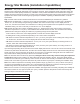
Energy Star Models (Installation Capabilities) IMPORTANT – This product** has been designed and manufactured to meet ENERGY STAR 6.1 criteria for energy efficiency when matched with appropriate coil components. However, proper refrigerant charge and proper air flow are critical to achieve rated capacity and efficiency. Installation of this product should follow the manufacturer’s refrigerant charging and air flow instructions.
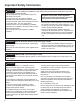
Important Safety Information WARNING For your safety, the information in this manual must be followed to minimize the risk of fire, electric shock, or personal injury. • Use this equipment only for its intended purpose as described in this manual. •T his heat pump must be properly installed in accordance with these instructions before it is used. •A ll wiring should be rated for the amperage value listed on the rating plate. Use only copper wiring.
Important Safety Information CAUTION It is highly recommended that you do not open or close the stop valves when the outdoor temperature is below -5°F (-21°C) as this may cause refrigerant leakage. Make sure power is turned on for at least 12 hours after periods of being powered down in an 32 °F (0° C) environment or lower. Do not touch the fins of the coil. Touching the coil fins could result in damage to the fins or personal injury such as skin rupture.
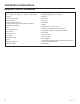
Installation Instructions Required Tools for Installation • 14/4 AWG stranded wire • 5/8” (16mm), 7/8” (22mm), 1” (25mm) or Adjustable Wrench • R-410A Refrigerant* • Adhesive tape* • Conduit cable clamp 1/2”* • Copper line set (for size, see table on page 15) • #2 phillips screwdriver • Drill • R-410A flaring tool • Hex wrench • Hole saw 2 1/4” • Insulation* • Refrigerant scale • Level • Manifold gauge set • Measuring tape 6 • Micron gauge • Mini-split adapter (5/16”F to 1/4”M) • Nitroge
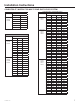
Installation Instructions COMPATIBILITY MATRIX FOR MULTI ZONE DUCTLESS SYSYTEM ASH218JCDDA1 & ASH220NCDWA Zones Combinations Unit A Unit B 7K 7K 7K 9K Two Zone Unit A Unit B Two Zone Unit C Unit D 9K 9K 7K 12K 9K 12K 12K 12K ASH324JCDDA1 & ASH324NCDWA Zones Two Zone Unit B Unit C Three Zone Unit A Unit B Unit C 31-5000560 Rev.
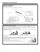
Installation Instructions INDOOR CLEARANCES (Appearance may vary) This picture is for reference only. Your product may look different. More than 4 inches Arrangement of piping directions Rear Left Rear Right Left Right Below More than 4 inches Wrap the insulation pipe with the finishing tape from the bottom to top. Condensate piping must have a downward slope of at least 1/4” per foot for proper drainage.
Installation Instructions Step 1 - Preparation Outdoor Unit Clearances NOTE: Fix the unit by inserting bolts, wire or other foundation options if there is danger that the unit will fall or turn over. NOTE: Place the unit on a level mounting base (or a plastic pedestal) for proper drainage. NOTE: Install the outdoor unit in a level position. Failure to do so may result in water leakage or accumulation.
Installation Instructions Step 1 - Preparation Cont. NOTES: •O D unit cannot hang from a ceiling or be stacked. • Ensure that accumulated snow, debris, etc… will not block the air inlet or the coil exchanger if installing the OD unit with a fence or rail guard around it. • Ensure ventilation in case of refrigerant leakage. R-410A is a safe, nontoxic, and nonflammable refrigerant. • Avoid installing the OD unit where corrosive gases, such as sulfur oxides, ammonia, and sulfurous gas are produced.
Installation Instructions Step 2 - Installation of the Indoor Unit (Cont.) C. Install the Tubing •A lways use new clean copper tubing. Never reuse tubing if replacing an existing system. • Measure and mark the location where the piping hole is to be drilled. • Follow these steps to move the drain pipe if pipe location will be on the left side of the unit. 1. Remove the stopper in the left drain hole and knockout the molded plug inside the port. 2.
Installation Instructions Step 2 - Installation of the Indoor Unit (Cont.) 1 2 3 A 1 L1 L2 2 3 Outdoor Unit B AC 208/230 Volt Supply L1toL1,L2toL2.ground to ground Power supply cable Indoor Unit A 1(N) 2(L) 3(C) Indoor Unit B 1(N) 2(L) 3(C) Note: Above diagram only demonstrates the wiring connection between outdoor & indoor for dual zone as an example. 12 31-5000560 Rev.
Installation Instructions Wall Brackets 2.795in (71mm) Ø 2 1/4in (57mm) 0.472in (12mm) 1.84in (46mm) Ø 2 1/4in (57mm) 0.236in (6mm) 40 N 35 N 4.882in (124mm) Ø 2 1/4in (57mm) 4.961in (126 mm) Ø 2 1/4in (57mm) 1.417in (36mm) 1.417in (36mm) 70 N 50 N 5.906in (150mm) Ø 2 1/4in (57mm) 3.150in (80mm) Ø 2 1/4in (57mm) 1.417in (36mm) 1.85in (47mm) 100 N 35 T 4.882in (124mm) Ø 2 1/4in (57mm) 4.961in (126mm) Ø 2 1/4in (57mm) 1.614in (41mm) 1.614in (41mm) 70 T 50 T 4.
Installation Instructions Step 3 - Installation of the Outdoor Unit A. Prepare the Outdoor Unit for Installation •R emove all packaging. • Place supplied vibration pads onto outdoor unit’s feet. • Use team lift to place the unit on a solid foundation, 8” above the average snowfall. Correct Installation B Attaching Drain Elbow to Outdoor Unit •A ttach the supplied drain elbow to the outdoor unit, if required. Connect extension piping as needed (not supplied).
Installation Instructions Step 3 - Installation of the Outdoor Unit (Cont.) Model: ASH218JCDDA1 ASH324JCDDA1 (Standard connection for indoor units A,B & C. Also, showing optional room card connections (future) and connections for a central controller) Outdoor Unit A B C Power Wiring To Service Disconnect 208/230 Volt Supply. L1 to L1. L2 to L2.
Installation Instructions Step 3 - Installation of the Outdoor Unit (Cont.) D. Wiring Check Test Turn off power at the disconnect. Move all dip switches in the SW1 bank to ON. When power is turned on, the LED display will alternate the compressor frequency and CH (check). The system will run through each unit (A, B, and C), cycling each EEV while testing the wiring. A successful test will be indicated by the corresponding LED displaying a constant green (1=A, 2=B, 3=C).
Installation Instructions Step 3 - Installation of the Outdoor Unit (Cont.) E. Install Copper Lineset • For ASH220NCDWA, ASH218JCDDA1, ASH324NCDWA, ASH324JCDDA1, ASH436JCDDA1, and ASH436NCDWA1 see table on page 16. • Cut the line set to length. • Place nut over the pipe and then flare with the R-410A flaring tool. NOTE: Follow standard practices for creating pipe flares. When cutting and reaming the tubing, use caution to prevent dirt or debris from entering the tubing.
Installation Instructions Step 3 - Installation of the Outdoor Unit (Cont.) H. Refrigerant Charging • Add any additional refrigerant after evacuation using a digital scale. NOTE: Charge liquid only. • Fill out the refrigerant charge label using indelible ink. • Place the factory refrigerant charge found in table on page 15. • Place the amount of additional refrigerant added in box number 2. • Add boxes 1 and 2 together and place the value in the sum box (D).
Limited Warranty For the product models listed on Attachment 1 (the “Product”), this Standard Limited Warranty is provided to the Original Owner of the Product: For The Period Of: GE Appliances Will Replace: 5 year limited parts warranty From the date of the original purchase This limited warranty cover all defects in workmanship or material for the mechanical and electrical parts contained in the Product (“Defective Parts”) for a period of 5 years from the Date of Purchase.
Limited Warranty 10 YEAR STANDARD REGISTERED LIMITED WARRANTY All “Indoor and Outdoor Products,” identified in Attachment 1, registered by the installer or the Original Owner within 60 days of the Date of Purchase shall receive a Standard Registered Limited Warranty, which shall be identical to the Standard Base Warranty, except that the Limited Parts Warranty shall be for a term of 10 Years and the Limited Compressor Warranty shall be for a term of 10 years.
Notes 31-5000560 Rev.
Instructions d’installation Multizone sans conduit avec unités intérieures murales hautes LIRE ATTENTIVEMENT. CONSERVEZ CES INSTRUCTIONS. 22 31-5000560 Rev.
Plage de fonctionnement Les informations suivantes répertorient la plage de fonctionnement spécifique à chaque modèle. ASH218JCDDA1/ ASH324JCDDA1/ ASH436JCDDA1 Cooling: 14°F to115°F Heating: -4°F to 75°F NOTES: • Lorsque la température extérieure chute en dessous de -30 ° C (-22 ° F), l’appareil s’arrête de fonctionner. L’appareil se rallume automatiquement lorsque la température dépasse la limite inférieure. Tenue de dossiers Merci d’avoir acheté ce produit GE Appliances.
MODÈLES ENERGY STAR (capacités d’installation) IMPORTANT – Ce produit** a été conçu et fabriqué pour satisfaire les critères de la norme ENERGY STAR 6.1 relatifs à l’efficacité énergétique lorsqu’on lui adjoint des composants de serpentin appropriés. Toutefois, une charge de réfrigérant et une circulation d’air appropriées sont essentiels pour atteindre la capacité et l’efficacité nominales.
Consignes de sécurité importantes AVERTISSEMENT Pour votre sécurité, les renseignements dans ce manuel doivent être observés afin de minimiser le risque d’incendie, de décharge électrique ou de blessure. •U tilisez cet équipement uniquement aux fins auxquelles il est fait mention dans ce manuel d’utilisation. •A vant son utilisation, ce thermopompe doit être installé correctement en conformité avec les instructions d’installation.
Consignes de sécurité importantes ATTENTION Il est fortement recommandé de ne pas ouvrir ou fermer les robinets d’arrêt lorsque la température extérieure est en dessous de -5 °F (-21 °C) car cela pourrait causer une fuite de réfrigérant. Assurez-vous que l’appareil est sous tension durant au moins 12 heures après des périodes de mise hors tension dans un environnement de 32 °F (0 °C) ou plus froid. Ne touchez pas aux ailettes du serpentin.
Instructions d’installation Outils nécessaires pour l’installation OUTILS DONT VOUS AUREZ BESOIN • Microvacuomètre • 5/8» (16mm), 7/8» (22mm), 1» (25mm) ou clé réglable • Azote* • Fil torsadé 14/4 • Frigorigène R-410A* • Ruban adhésif* • Bride de câble de conduit 1/2 po* • Tuyauterie en cuivre (voir tableau page 33 pour dimensions) • Tournevis à tête cruciforme no 2 • Perceuse • Outil à évaser R-410A° • Clé hexagonale • Scie-cloche 2 1/4 po • Isolant* • Balance de réfrigérant • Niveau • Manomètre de pr
Instructions d’installation MATRICE DE COMPATIBILITÉ POUR SYSTÈME SANS CONDUITS MULTIZONE ASH218JCDDA1 & ASH220NCDWA Zones Combinaisons Unité A Unité B 7K 7K 7K 9K 9K 9K 7K 12K 9K 12K 12K 12K Deux zones Unité A Unité B ASH324JCDDA1 & ASH324NCDWA Zones Combinations Unité A Deux zones Unité B Unité C Trois zones Unit A Unit B Unit C Unité B Unité C — 7K 7K — 7K 9K — 9K 9K — 7K 12K — 9K 12K — 12K 12K — 7K 18K — 9K 18K — 12K 18K 7K 7K 7K 7K 7K 9K 7K 9K 9K
Instructions d’installation DÉGAGEMENTS INTÉRIEURS (L’aspect peut varier) Cette illustration est pour référence seulement. L’aspect de votre produit peut être différent. Lisez votre manuel avant l’installation. Expliquez le fonctionnement de l’appareil à l’utilisateur selon ce manuel. Plus de 4 pouces Directions des tuyauteries Plus de 4 pouces Arrière gauche gauche Arrière droite droite Dessous Envelopper le tuyau d’isolation avec du ruban definition de bas en haut.
Instructions d’installation Étape 1 – Préparation DÉGAGEMENTS EXTÉRIEURE REMARQUE: Fixez l’unité en insérant des boulons, des fils métalliques ou d’autres moyens d’arrimage si l’unité risque de tomber ou de basculer. REMARQUE: Placez l’appareil sur une base de montage de niveau (ou sur un socle en plastique) pour un drainage adéquat. REMARQUE: Installez l’unité extérieure dans une position horizontale. Sinon, cela pourrait entraîner une fuite d’eau ou une accumulation d’eau.
Instructions d’installation Étape 1 – Préparation (Suite) REMARQUES: •L ’unité extérieure ne peut pas s’accrocher à un plafond ou s’empiler. • Assurez-vous que l’accumulation de neige, de débris ou d’autres matières n’obstruent pas l’entrée d’air ou l’échangeur du serpentin si une clôture ou un garde-fou entoure l’unité • Assurez-vous que la ventilation sera suffisante en cas de fuite de frigorigène. Le R-410A est un frigorigène sûr, non toxique et inflammable.
Instructions d’installation Étape 2 – Installation de l’unité intérieure (Suite) C. Installation de l’orifice de tuyauterie •U tilisez toujours une tuyauterie de cuivre propre. Ne réutilisez jamais la tuyauterie si vous remplacez un système existant. • Mesurez et marquez l’endroit où l’orifice de tuyauterie sera percé. • Follow these steps to move the drain pipe if pipe location will be on the left side of the unit. 1.
Instructions d’installation Étape 2 – Installation de l’unité intérieure (Suite) 1 2 3 A 1 L1 L2 2 3 Outdoor Unit B AC 208/230 Volt Supply L1toL1,L2toL2.ground to ground Power supply cable Indoor Unit A 1(N) 2(L) 3(C) Indoor Unit B 1(N) 2(L) 3(C) Remarque : Le schéma ci-dessus illustre seulement les connexions entre les unités intérieure et extérieure dans le cas d’une zone double à titre d’exemple. 31-5000560 Rev.
Instructions d’installation Supports muraux 2.795in (71mm) Ø 2 1/4in (57mm) 0.472in (12mm) 1.84in (46mm) Ø 2 1/4in (57mm) 0.236in (6mm) 40 N 35 N 4.882in (124mm) Ø 2 1/4in (57mm) 4.961in (126 mm) Ø 2 1/4in (57mm) 1.417in (36mm) 1.417in (36mm) 70 N 50 N 5.906in (150mm) Ø 2 1/4in (57mm) 3.150in (80mm) Ø 2 1/4in (57mm) 1.417in (36mm) 1.85in (47mm) 100 N 35 T 4.882in (124mm) Ø 2 1/4in (57mm) 4.961in (126mm) Ø 2 1/4in (57mm) 1.614in (41mm) 1.614in (41mm) 70 T 50 T 4.
Instructions d’installation Étape 3 – Installation de l’unité extérieure A. Préparation de l’unité extérieure pour l’installation • Retirez tout l’emballage. • Placezles coussinets antivibrations fournis sur les pieds de l’unité extérieure. •U tilisez l’équipe de levage pour placer l’appareil sur une base solide, à 8 “au-dessus de la moyenne des chutes de neige. Installation correcte B.
Instructions d’installation Étape 3 – Installation de l’unité extérieure (Suite) Modèle : ASH218JCDDA1 ASH324JCDDA1 (Connexion standard des unités intérieures A,B et C. Aussi illustration des connexions d’une carte de chambre en option (future) et des connexions d’une commande centrale.) Unité extérieure A B C Câblage d’alimentation Pour déconnecter le service Alimentation 208/230 volts. L1 à L1. L2 à L2.
Instructions d’installation Étape 3 – Installation de l’unité extérieure (Suite) D. Test de vérification du câblage Coupez l’alimentation électrique au disjoncteur. Mettez tous les commutateurs DIP du groupe SW1 sur ON. Lorsque l’alimentation électrique est rétablie, l’écran DEL va alterner entre la fréquence du compresseur et le code CH (check : vérification).
Instructions d’installation Paso 3 – Instalación de la Unidad de Exterior E. Instale el Juego de Cables de Cobre •P ara ASH220NCDWA, ASH218JCDDA1, ASH324NCDWA, ASH324JCDDA1, ASH436JCDDA1, y ASH436NCDWA1 vea la tabla de la página 37. • Corte el juego de cables de acuerdo a la longitud. •C oloque la tuerca sobre la tubería y luego abocarde con la herramienta de abocardado R-410A. NOTA: Siga las prácticas estándares para realizar el agrandamiento de tuberías.
Instructions d’installation Paso 3 – Instalación de la Unidad de Exterior H. Carga del Refrigerante Si la instalación requirió más de 25 pies de un juego de cables de cobre, entonces agregue 0.2 onzas de R-410A al sistema por cada pie adicional del juego de cables. • Agregue cada refrigerante adicional luego de la evacuación usando una balanza digital. NOTA: Cargue líquido únicamente. • Complete la etiqueta de carga de refrigerante usando tinta indeleble.
Garantie limitée Cette Garantie limitée standard est attribuée à l’Acheteur initial du Produit pour les modèles énumérés sous l’Annexe 1 (le « Produit ») :: For The Period Of: GE Appliances Will Replace: Garantie limitée de 5 ans sur les pièces Cette garantie couvre tous les vices de matière et de fabrication des pièces mécaniques et électriques contenues dans le Produit (« Pièces défectueuses ») durant une période de cinq (5) ans à partir de la Date d’achat.
Garantie limitée GARANTIE LIMITÉE ENREGISTRÉE STANDARD DE 10 ANS Tous les « Produits intérieurs et extérieurs » identifiés dans l’Annexe 1, enregistrés par l’installateur ou le Propriétaire initial dans un délai de soixante (60) jours à partir de la Date d’achat, recevront une Garantie limitée enregistrée standard qui sera identique à la Garantie de base standard, excepté que la période de la Garantie limitée sur les pièces et la Garantie limitée sur le compresseur sera de dix (10) ans.
Notas 42 31-5000560 Rev.
Instrucciones de instalación Multizona sin ductos con unidades interiores de pared alta LEA CUIDADOSAMENTE. GUARDE ESTAS INSTRUCCIONES. 31-5000560 Rev.
Rango de operación The following information lists the operating range specific to each model. ASH218JCDDA1/ ASH324JCDDA1/ ASH436JCDDA1 Cooling: 14°F to115°F Heating: -4°F to 75°F ASH220NCDWA/ ASH324NCDWA / ASH436NCDWA1 Cooling: 14°F to115°F Heating: -15°F to 75°F NOTAS: • Cuando la temperatura exterior cae por debajo de -30 ° C (-22 ° F), la unidad deja de funcionar. La unidad se enciende automáticamente cuando la temperatura excede el límite inferior.
MODELOS DE ENERGY STAR (Capacidades de Instalación) IMPORTANTE – Este producto** fue diseñado y fabricado para cubrir los criterios de ENERGY STAR 6.1 en relación a eficiencia energética al ser usado con los componentes bobinados apropiados. Sin embargo, la carga correcta de refrigerante y la circulación de aire apropiado son críticos para lograr la capacidad y eficiencia indicadas.
Instrucciones de instalación ADVERTENCIA Para su seguridad, siga las instrucciones de este manual a fin de minimizar riesgos de incendio, descargas eléctricas o lesiones personales. •U se este equipo sólo para su propósito original, como se Si es necesario realizar un servicio que requiere describe en el Manual del Usuario.
Instrucciones de instalación PRECAUCIÓN Se recomienda encarecidamente que no abra ni cierre las válvulas de cierre cuando la temperatura exterior sea inferior a -5 ° F (-21 ° C), ya que esto puede causar fugas de refrigerante. Asegúrese de que el encendido esté activado durante por lo menos 12 horas luego de períodos donde haya estado apagado en un ambiente de 32 °F (0° C) o menos. No toque las aletas de la bobina.
Instrucciones de instalación Herramientas Requeridas para la Instalación HERRAMIENTAS NECESARIAS • Cinta de Medición • Llave de 17mm, 22mm, 26mm o Llave Ajustable • Adaptador para Mini Split (5/16” H a 1/4” M) • Cable Trenzado AWG de 14/4 • Refrigerante 410A* • Cinta Adhesiva* • Medidor de Micrones • Nitrógeno* • Cortatubos • Sujetador del Cable Conductor de 1/2”* • Tubería de PVC (opcional) • J uego de Cables de Cobre (para consultar tamaños, lea la tabla de la página 51) • Cuchillo con Filo • Es
Instrucciones de instalación MATRIZ DE COMPATIBILIDAD PARA EL SISTEMA SIN CONDUCTO MULTI ZONA ASH218JCDDA1 & ASH220NCDWA Zones Unité A Unité B 7K 7K 7K 9K 9K 9K 7K 12K 9K 12K 12K 12K Deux zones Unité A Unité B ASH436JCDDA1 & ASH436NCDWA1 Combinaisons Zones Combinaisons Deux zones Unité C Unité D Trois zones ASH324JCDDA1 & ASH324NCDWA Zones Deux zones Unité B Unité C Trois zones Unit A Unit B Unit C Combinations Unité A Unité B Unité C — 7K 7K — 7K 9K — 9K 9K — 7K 12K —
Instrucciones de instalación ESPACIOS INTERIORES (El aspecto puede variar) Esta imagen sólo sirve como referencia. El aspecto de su producto podrá ser diferente. Lea el manual antes de realizar la instalación. Explique el funcionamiento de la unidad al usuario, de acuerdo con este manual.
Instrucciones de instalación Paso 1 - Preparación ESPACIOS EXTERIOR NOTA: Si existe peligro de que la unidad caiga o se dé vuelta, ajuste la unidad insertando tornillos, alambres u otras opciones de soporte. NOTA: Coloque la unidad sobre una base de montaje nivelada (o un pedestal de plástico) para un drenaje adecuado. NOTA: Instale la unidad exterior en una posición nivelada. De lo contrario, se pueden producir fugas o acumulación de agua.
Instrucciones de instalación Paso 1 - Preparación (Cont.) NOTAS: •L a unidad de exterior no podrá ser colgada de un cielorraso ni ser apilada. •S i instalará la unidad exterior con una valla o un protector a su alrededor, asegúrese de que la nieve, polvo, etc. acumulados no bloqueen la entrada de aire o el intercambiador de la bobina. • Asegúrese de que haya ventilación en caso de pérdidas de refrigerante. El R-410A es un refrigerante seguro, no tóxico y no inflamable.
Instrucciones de instalación Paso 2 – Instalación de la Unidad de Interior (Cont.) C. Instale el Agujero de la Tubería •S iempre use tuberías de cobre nuevas y limpias. Nunca vuelva a usar una tubería si se está reemplazando un sistema anterior. • Mida y marque la ubicación donde el agujero de la tubería será perforado. •S i la ubicación de la tubería estará sobre el lado izquierdo de la unidad, siga estos pasos para mover la tubería de drenaje. 1.
Instrucciones de instalación Paso 2 – Instalación de la Unidad de Interior (Cont.) 1 2 3 A 1 L1 L2 2 3 Outdoor Unit B AC 208/230 Volt Supply L1toL1,L2toL2.ground to ground Power supply cable Indoor Unit A 1(N) 2(L) 3(C) Indoor Unit B 1(N) 2(L) 3(C) Nota: El diagrama anterior sólo muestra, a modo de ejemplo, la conexión del cableado entre interior y exterior para zona dual. 54 31-5000560 Rev.
Instrucciones de instalación Soportes de Pared 2.795in (71mm) Ø 2 1/4in (57mm) 0.472in (12mm) 1.84in (46mm) Ø 2 1/4in (57mm) 0.236in (6mm) 40 N 35 N 4.882in (124mm) Ø 2 1/4in (57mm) 4.961in (126 mm) Ø 2 1/4in (57mm) 1.417in (36mm) 1.417in (36mm) 70 N 50 N 5.906in (150mm) Ø 2 1/4in (57mm) 3.150in (80mm) Ø 2 1/4in (57mm) 1.417in (36mm) 1.85in (47mm) 100 N 35 T 4.882in (124mm) Ø 2 1/4in (57mm) 4.961in (126mm) Ø 2 1/4in (57mm) 1.614in (41mm) 1.614in (41mm) 70 T 50 T 4.
Instrucciones de instalación Paso 3 – Instalación de la Unidad de Exterior A. P repare la Unidad de Exterior para su Instalación • Retire todo el embalaje. • Coloque las almohadillas de vibración suministradas sobre los pies de la unidad de exterior. • Use el equipo de elevación para colocar la unidad sobre una base sólida, 8 “por encima de la nevada promedio. Instalación correcta B.
Instrucciones de instalación Paso 3 – Instalación de la Unidad de Exterior Modelo: ASH218JCDDA1 ASH324JCDDA1 (Conexión estándar para las unidades interiores A, B y C. Además, se muestran conexiones (futuras) de tarjeta opcionales para sala y conexiones para un controlador central) Unidad exterior A B C Cableado de energía Para desconectar el servicio Suministro de 208/230 voltios. L1 a L1. L2 a L2.
Instrucciones de instalación Paso 3 – Instalación de la Unidad de Exterior D. Prueba de Control del Cableado Desconecte la entrada de corriente. Mueva todos los interruptores DIP del banco SW1 a ON (Encendido). Una vez encendida la corriente, la pantalla LED alternará la frecuencia del compresor y CH (Control). El sistema funcionará a través de cada unidad (A, B y C), realizando ciclos en cada EEV (Válvula de Expansión Electrónica) mientras controla el cableado.
Instrucciones de instalación Paso 3 – Instalación de la Unidad de Exterior E. Instale el Juego de Cables de Cobre •P ara ASH220NCDWA, ASH218JCDDA1, ASH324NCDWA, ASH324JCDDA1, ASH436JCDDA1, y ASH436NCDWA1 vea la tabla de la página 58. • Corte el juego de cables de acuerdo a la longitud. •C oloque la tuerca sobre la tubería y luego abocarde con la herramienta de abocardado R-410A. NOTA: Siga las prácticas estándares para realizar el agrandamiento de tuberías.
Instrucciones de instalación Paso 3 – Instalación de la Unidad de Exterior H. Carga del Refrigerante Si la instalación requirió más de 25 pies de un juego de cables de cobre, entonces agregue 0.2 onzas de R-410A al sistema por cada pie adicional del juego de cables. • Agregue cada refrigerante adicional luego de la evacuación usando una balanza digital. NOTA: Cargue líquido únicamente. • Complete la etiqueta de carga de refrigerante usando tinta indeleble.
Garantía Limitada Para los modelos de los productos que figuran en el Adjunto 1 (el “Producto”), esta Garantía Estándar Limitada es provista al Dueño Original del Producto: For The Period Of: GE Appliances Will Replace: Garantía limitada de piezas de 5 años desde la fecha de compra Esta garantía cubre todos los defectos de fabricación o de los materiales de las piezas mecánicas y eléctricas pertenecientes al Producto (“Piezas Defectuosas”) durante un período de 5 años desde la Fecha de Compra.
Garantía Limitada GARANTÍA LIMITADA ESTÁNDAR REGISTRADA POR 10 AÑOS Todos los “Productos de Interior y Exterior”, identificados en el Adjunto 1, registrados por el instalador o el Dueño Original dentro de los 60 días desde la Fecha de Compra recibirán una Garantía Limitada Estándar Registrada, la cual será idéntica a la Garantía Estándar Base, excepto que la Garantía de Piezas Limitada tendrá validez por el término de 10 Años y la Garantía Limitada del Compresor será por un término de 10 años.
Notes 31-5000560 Rev.
IMPORTANT Do Not Return This Product To The Store If you have a problem with this product, please call 1-844-487-9443 for the name and telephone number of the nearest authorized service center. DATED PROOF OF PURCHASE REQUIRED FOR WARRANTY SERVICE IMPORTANT Ne pas Réexpédier ce Produit au Magasin En cas de problème avec ce produit, veuillez composer le 1-844-487-9443 pour connaître le nom et le numéro de téléphone du centre de service autorisé le plus proche.