Installation Instructions 36" Built-In All-Refrigerators and All-Freezers 31-46148 224D2601P001 06-08 JR monogram.
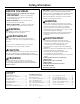
Safety Information Skill Level - Installation of this product requires basic mechanical, carpentry and plumbing skills. Proper installation is the responsibility of the installer. Product failure due to improper installation is not covered under the GE Appliance Warranty. See the Owner’s Manual for warranty information. BEFORE YOU BEGIN Read these instructions completely and carefully. • IMPORTANT - Save these instructions for local inspector’s use. Observe all governing codes and ordinances.
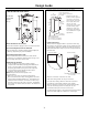
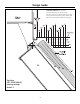
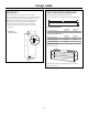
Design Guide DIMENSIONS AND CLEARANCES THE INSTALLATION SPACE 35" Case Width The finished cutout width must be 35-1/2". 25-3/8" Framed Models 25-3/4" Stainless Steel Models Case Depth *84" From Floor to Top Frame *83-1/2" at Rear * Shipping height. The product can be adjusted to fit into a cutout that is 83-1/2" min. to 84-1/2" max. height. Note that the top case trim at the front is 1/2" higher and will overlap upper cabinetry or soffit.
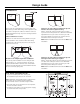
Design Guide CLEARANCES 130° Door Swing 25" Min. to Wall 2" 15" 130° Clearances for two products installed side-by-side with the same (left or right) door swing Allow 2" minimum clearance between the products to prevent door swing interference. Order the WX14X99 adjustable door stop to reduce the factory set 130° door swing. Allow 15" minimum to a wall to achieve full drawer extension and pan removal. NOTE: ZUG2 and ZUGSS2 Grille Panel Kit will NOT fit this installation.
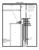
Design Guide Frameless Cabinets: The case trim overlaps cabinets at the top and sides. Therefore, frameless cabinets may require filler strips to prevent interference with cabinet door swing. The opening must allow for filler strips.
Design Guide Frameless Cabinets: The case trim overlaps Case Trim cabinets at the top and sides. Therefore, frameless cabinets may require filler strips to prevent interference with cabinet door swing. 23-7/8" The opening must allow From Rear of for filler strips.
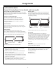
Design Guide CUSTOMIZATION BASICS: Framed Or Overlay Panels, Custom Handles and Accessory Kits Professional Style Stainless Steel Models Stainless steel wrapped refrigerators have beveled edges and professional-style handles. These models are shipped ready for installation. Overlay panels You may also choose to install custom overlay panels from your cabinet manufacturer. This design provides a seamless appearance which integrates smoothly with surrounding cabinetry.
Design Guide 1/4" FRAMED PANEL DIMENSIONS If you choose to install framed panels, they must be cut to the dimensions shown. The panels will slide into the frame on the door and grille. Door If the custom panel is less than 1/4" thick and if it fits loosely in the door frame, it can be backed up with a piece of filler material or foam tape to improve the fit. 5/16" Trim Reveal 1/4" Panel IMPORTANT NOTE: Maximum weight for door panel is 67 pounds.
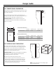
Design Guide SIDE PANELS ZUG2 GRILLE PANEL DIMENSIONS Side panels must be used whenever the sides of the unit will be exposed. The 1/4" side panels will slip into the side case trim. Secure the panels to the unit with stick-on hook and loop fastener strips. Order the side panels from the cabinet manufacturer. • Cut a notch in the top front corner as shown to allow clearance for corner keys in the front side trim.
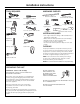
Installation Instructions TOOLS REQUIRED HARDWARE SUPPLIED Custom handle trim Tin snips to cut banding #2 Phillips screwdriver Anti-Tip bracket (Secured to side of unit.) 3 lag screws Stepladder Drill and 1/2", 3/16" bits Water filter bypass plug 2 Hair Pin Cotters Bucket 1/4", 1/2", 5/16", 7/16" socket 4 Washers 5 toggles with bolts Supplied Toekick Toekick (Secured to side of unit.
Installation Instructions CAUTION: STEP 1 REMOVE PACKAGING DO NOT ATTEMPT TO ROLL UNIT OFF SKID. CAUTION: Product is much heavier at the top than at the bottom – be careful when moving. When using a hand truck, handle from side only. PRUDENCE: PRUDENCE: IL NE FAUT PAS ESSAYER DE FAIRE ROULER L’ APPAREIL MÉNAGER POUR L'ENLEVER DE LAY PALETTE. Le produit est beaucoup plus lourd en haut qu’en bas. Il faut être prudent lors des déplacements.
Installation Instructions STEP 4 INSTALL ANTI-TIP BRACKET WARNING: ANTI-TIP PRECAUTIONS The unit is top-heavy and must be secured to prevent the possibility of tipping forward. ATTENTION: PRECAUTIONS CONTRE LES BASCULEMENTS L’appareil ménager est beaucoup plus lourd en haut et il faut le maintenir en place pour éviter la possibilité de son basculement vers l’avant. • The kit supplied with the unit contains 2 lag bolts and 4 toggles with bolts. The wall bracket will be attached to the wall in 4 places.
Installation Instructions STEP 4 INSTALL ANTI-TIP BRACKET (cont.) Install Wall Toggles: The wall toggles and bolts can be ordered as Service Kit #WR49X10193. Wall toggles are installed in the drywall and metal studs for stability. Install the wall toggles as follows: • Drill 1/2" holes at the wall markings made in the holes at the ends of the wall bracket. • Hold the metal channel flat against the plastic straps and slide the channel through the hole.
Installation Instructions Power Cord Locate the power cord inside the left cavity. If it has not been adjusted so the plug is easily accessible, do so now. STEP 4 INSTALL ANTI-TIP BRACKET (cont.) Remove Grilles for Access to Power Cord and Anti-tip Locking Hooks “L” Bolt Fresh Food Unit • Open the access door. • Using a 1/4" hex driver, remove the 2 screws at the bottom of the grille. • Pull the bottom of the grille forward, down and out to remove.
Installation Instructions STEP 5 LEVEL UNIT All models have 4-point leveling. The front is supported by leveling legs; the rear is supported by adjustable wheels. Both are accessible from the front of the unit. • To level the back of the unit, turn the 7/16" hex nut located above the front wheels. Turn clockwise to raise or counterclockwise to lower the unit. • For front leveling, use a 1-1/4" open-end wrench. • Adjust height of unit to match installation cutout opening 83-1/2 to 84-1/2".
Installation Instructions STEP 6 SECURE UNIT TO WALL • The “L” rods can be found in the upper left and right corners of the unit in the access compartment. Look through the access compartment to make sure the rods line up with the anti-tip bracket. • There are 2 washers and a hair pin cotter per rod. Remove the washers and hair pin cotter from the end of the rod. • Rotate and move the “L” rod into the slot in the anti-tip bracket tab.
Installation Instructions STEP 7 ADJUST DOOR SWING STEP 8 INSTALL GRILLE PANEL (TRIMMED MODELS ONLY) NOTE: This refrigerator has a 2-position door stop. When space does not allow the door to swing open fully to 130°, you may change the door swing to a 90° opening. Skip this step if door opening is satisfactory for your installation situation. • Raise the access panel to the stop position.
Installation Instructions Right hand models shown. Use the same instructions for left hand models. IF YOU ARE INSTALLING OVERLAY PANELS, GO TO STEP 10A. STEP 9 INSTALL FRAMED PANELS (TRIMMED MODELS ONLY) Handle Trim Door Trim Door Use Front Holes to Secure Trim Use Rear Holes to Secure Handle Install Door Panel: • Open the door to 90°. Remove the 6 Phillips head screws from the door handle. • Remove the handle. Retain all screws. • Remove the 6 screws holding the trim, lift off the trim.
Installation Instructions Right hand models shown. Use the same instructions for left hand models. STEP 9A INSTALL OVERLAY PANELS Door Trim Handle Trim Door Move Forward For 3/4" Panel Use Front Holes to Secure Handle Use Rear Holes to Secure Trim Supplied handle shown in the overlay panel position. Install Door Panel: • Open the door to 90°. Remove the 6 Phillips head screws from the door handle. • Remove the handle. Retain all screws. • Remove the 6 screws holding the trim, lift off the trim.
Installation Instructions STEP 11 START ICEMAKER STEP 10 CONNECT WATER SUPPLY (FREEZER MODELS ONLY) Icemaker House Water Supply Freezer Water Supply Power Switch • Locate and bring the tubing to the front of the cabinet. • Turn the water on to flush debris from the line. Run about a quart of water through the tubing into a bucket, then shut off the water. Copper Tubing: • Slip a 1/4" nut and ferrule (provided) over both ends of the copper tubing.
Notes 21
Notes 22
Notes 23
NOTE: While performing installations described in this book, safety glasses or goggles should be worn. For Monogram® local service in your area, call 1.800.444.1845. NOTE: Product improvement is a continuing endeavor at General Electric. Therefore, materials, appearance and specifications are subject to change without notice. 31-46148 224D2601P001 06-08 JR Printed in the United States GE Consumer & Industrial Appliances General Electric Company Louisville, KY 40225 ge.