
Appliance Trim Kit User Manual


Table Of Contents
- Chapter 1 Overview
- Chapter 2 C400 Panel Controller Hardware
- General Information
- Genius Panel Controller (C400)
- Specifications
- Overview of Connections and Operational Elements
- VDC Power Supply (item 2, Figure 2-2)
- IF0 - RS-232, Non-isolated (item 3, Figure 2-2)
- Genius Bus Connector, Isolated (item 4, Figure 2-2)
- Mode Switch (item 6, Figure 2-2)
- Device Number Switches (item 8, Figure 2-2)
- Lithium Battery (item 7, Figure 2-2)
- Reset Button (item 9, Figure 2-2)
- Operating the C400 Controller
- Chapter 3 Quick Start
- Calling the Setup Program
- Language Selection
- Installation Menu
- Pull-Down Menus (Main Menu)
- Window Name
- Selection Windows
- Context-Sensitive Help Screens
- Screen Elements
- Connection to a GE Fanuc PLC via Genius
- Internal Connection
- Genius Internal Connection
- Picture 1
- Picture 2
- Picture 3
- Genius Device Connection
- Genius Internal Connection
- Internal Connection
- Picture for a Communications Error
- Picture Binding Overview
- Picture List Organization
- Chapter 4 Configuring Communication with the PLC
- Chapter 5 PCS Connection Editor
- Chapter 6 Demo Project
- Appendix A Cabling Information
- Appendix B Errors/Troubleshooting
- Index
6 - 12 PANELWARE MMI Application Manual for GE Fanuc Genius Protocol - June 1995 GFK-1115
6
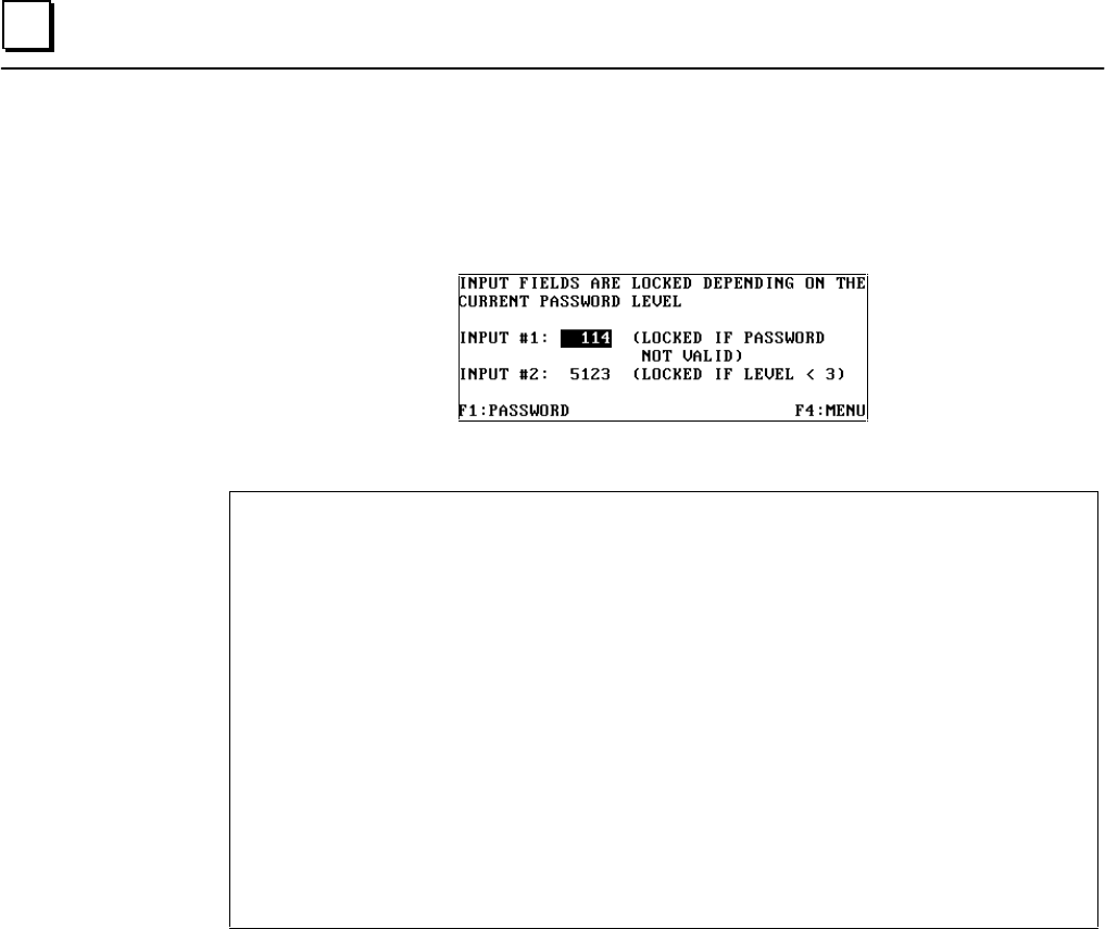
LOCKED INPUT Picture
If you press the F1 function key while in the INPUT PASSWORD picture, the LOCKED INPUT
picture appears on the Panel display:
Key LEDs:
If an invalid password has been entered, you cannot change the value for INPUT #1. The value for
INPUT #2 can only be changed if the proper password for password level 3 is entered.
With keys +p+ and +n+, you can switch to the other input field if allowed (depends on your
password level).
Keys F1 and F4 are used to switch to one of the following pictures:
F1 Switches back to the INPUT PASSWORD picture
The entry of a password and its function is performed in this picture.
F4 Changes picture back to the main menu.