
Appliance Trim Kit User Manual


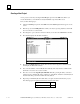


Table Of Contents
- Chapter 1 Overview
- Chapter 2 C400 Panel Controller Hardware
- General Information
- Genius Panel Controller (C400)
- Specifications
- Overview of Connections and Operational Elements
- VDC Power Supply (item 2, Figure 2-2)
- IF0 - RS-232, Non-isolated (item 3, Figure 2-2)
- Genius Bus Connector, Isolated (item 4, Figure 2-2)
- Mode Switch (item 6, Figure 2-2)
- Device Number Switches (item 8, Figure 2-2)
- Lithium Battery (item 7, Figure 2-2)
- Reset Button (item 9, Figure 2-2)
- Operating the C400 Controller
- Chapter 3 Quick Start
- Calling the Setup Program
- Language Selection
- Installation Menu
- Pull-Down Menus (Main Menu)
- Window Name
- Selection Windows
- Context-Sensitive Help Screens
- Screen Elements
- Connection to a GE Fanuc PLC via Genius
- Internal Connection
- Genius Internal Connection
- Picture 1
- Picture 2
- Picture 3
- Genius Device Connection
- Genius Internal Connection
- Internal Connection
- Picture for a Communications Error
- Picture Binding Overview
- Picture List Organization
- Chapter 4 Configuring Communication with the PLC
- Chapter 5 PCS Connection Editor
- Chapter 6 Demo Project
- Appendix A Cabling Information
- Appendix B Errors/Troubleshooting
- Index
GFK-1115 Chapter 6 Demo Project 6 - 19
6
■ If all of the entries that are required have been defined, you can confirm the whole definition
by pressing the F4 Accept key, which closes and saves the hardware definition. The window
is closed and the main menu appears. At the top of the screen, the project name
DEMO_PRO is displayed. If, instead of F4, either the Esc or F10 Exit key is pressed, all
entries are disregarded and none are saved.
Note
Further information on the use of the project editor can be found in chapter 4 of
the PANELWARE™ Software Configuration Reference Manual.
Selecting the Connections
Every PLC that is connected with a modular PANELWARE Panel must be defined in the
connection list. Each connection has a separate list, called the Variable Assignment Table (VAT).
The VAT contains all variables that are used in the project and their assignments to physical PLC
addresses.
Execute the following steps to define the connections used in the demo:
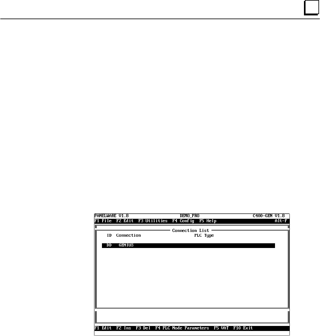
1
. Select the Connection function from the Edit menu. The Connection List window
appears. The connections that are already defined are shown in this list. The connection
with the ID DD is automatically inserted when a new project is created.