
Appliance Trim Kit User Manual
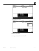


Table Of Contents
- Chapter 1 Overview
- Chapter 2 C400 Panel Controller Hardware
- General Information
- Genius Panel Controller (C400)
- Specifications
- Overview of Connections and Operational Elements
- VDC Power Supply (item 2, Figure 2-2)
- IF0 - RS-232, Non-isolated (item 3, Figure 2-2)
- Genius Bus Connector, Isolated (item 4, Figure 2-2)
- Mode Switch (item 6, Figure 2-2)
- Device Number Switches (item 8, Figure 2-2)
- Lithium Battery (item 7, Figure 2-2)
- Reset Button (item 9, Figure 2-2)
- Operating the C400 Controller
- Chapter 3 Quick Start
- Calling the Setup Program
- Language Selection
- Installation Menu
- Pull-Down Menus (Main Menu)
- Window Name
- Selection Windows
- Context-Sensitive Help Screens
- Screen Elements
- Connection to a GE Fanuc PLC via Genius
- Internal Connection
- Genius Internal Connection
- Picture 1
- Picture 2
- Picture 3
- Genius Device Connection
- Genius Internal Connection
- Internal Connection
- Picture for a Communications Error
- Picture Binding Overview
- Picture List Organization
- Chapter 4 Configuring Communication with the PLC
- Chapter 5 PCS Connection Editor
- Chapter 6 Demo Project
- Appendix A Cabling Information
- Appendix B Errors/Troubleshooting
- Index
6 - 32 PANELWARE MMI Application Manual for GE Fanuc Genius Protocol - June 1995 GFK-1115
6
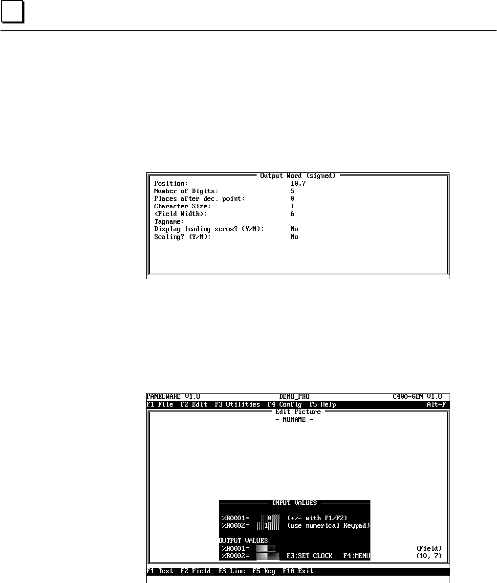
6. Insert an output field into the picture. The value that is entered in the second input field will
be displayed in this output field. This is done as follows:
● Position the cursor at (10,7).
● Press F2 Field.
● Select the Output Field entry from the Field class window and press the ↵↵ key.
● Select the entry Output Word (signed) from Select field type window. This opens a
window in which you can enter or change the parameters for the selected input field:
● Now, enter
OUT_INT
as the Destination Tagname and confirm your entry with ↵↵.The
declaration of this address is done along with all other variables in the connection editor
(see “Connections” in this chapter).
● In order to display preceding zeros, move the cursor to the Display leading zeros line.
Enter
Y
and then ↵↵ to activate the preceding zero display.
● End the entry with F4 Accept. The window Output Word (signed) is closed. The output
field is then seen in the picture: