
Appliance Trim Kit User Manual


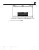


Table Of Contents
- Chapter 1 Overview
- Chapter 2 C400 Panel Controller Hardware
- General Information
- Genius Panel Controller (C400)
- Specifications
- Overview of Connections and Operational Elements
- VDC Power Supply (item 2, Figure 2-2)
- IF0 - RS-232, Non-isolated (item 3, Figure 2-2)
- Genius Bus Connector, Isolated (item 4, Figure 2-2)
- Mode Switch (item 6, Figure 2-2)
- Device Number Switches (item 8, Figure 2-2)
- Lithium Battery (item 7, Figure 2-2)
- Reset Button (item 9, Figure 2-2)
- Operating the C400 Controller
- Chapter 3 Quick Start
- Calling the Setup Program
- Language Selection
- Installation Menu
- Pull-Down Menus (Main Menu)
- Window Name
- Selection Windows
- Context-Sensitive Help Screens
- Screen Elements
- Connection to a GE Fanuc PLC via Genius
- Internal Connection
- Genius Internal Connection
- Picture 1
- Picture 2
- Picture 3
- Genius Device Connection
- Genius Internal Connection
- Internal Connection
- Picture for a Communications Error
- Picture Binding Overview
- Picture List Organization
- Chapter 4 Configuring Communication with the PLC
- Chapter 5 PCS Connection Editor
- Chapter 6 Demo Project
- Appendix A Cabling Information
- Appendix B Errors/Troubleshooting
- Index
6 - 48 PANELWARE MMI Application Manual for GE Fanuc Genius Protocol - June 1995 GFK-1115
6
ALARM Picture (Alarm List)
This picture shows a list of active alarms. The
alarm bit field (16 bits in the demo project) is
read from the PLC. Every bit represents an alarm.
If an alarm occurs (bit changes from 0 to 1), it
will appear in the alarm list. This alarm list can
be displayed with the alarm field Active Alarm.
To display a list of four active alarms (as shown in the picture above), insert four fields into the
picture.
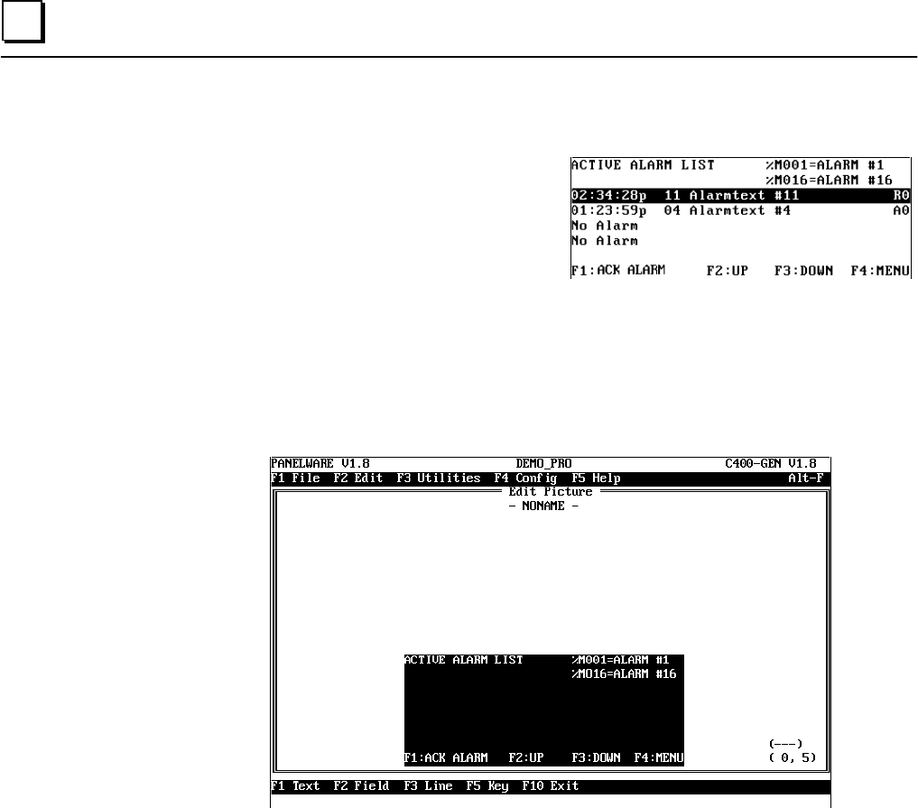
Execute the following steps to create this picture:
1. Call the picture editor from the main menu with key combination Ctrl + B (see page 6-23).
2. Insert all lines and text into the rectangle so that your picture looks like the one below:
3. Now insert the first alarm field Active Alarm in cursor position 0,2 with the following
parameters:
Position:.............................................0,2
Field Width:.......................................
40
F key for Acknowledge:......................
F1
Function Key for Up:..........................
F2
Function Key for Down:.....................
F3
4. The next three fields are inserted with the same parameters, each field a line lower in the
picture. The picture should then look like this: