
Appliance Trim Kit User Manual


Table Of Contents
- Chapter 1 Overview
- Chapter 2 C400 Panel Controller Hardware
- General Information
- Genius Panel Controller (C400)
- Specifications
- Overview of Connections and Operational Elements
- VDC Power Supply (item 2, Figure 2-2)
- IF0 - RS-232, Non-isolated (item 3, Figure 2-2)
- Genius Bus Connector, Isolated (item 4, Figure 2-2)
- Mode Switch (item 6, Figure 2-2)
- Device Number Switches (item 8, Figure 2-2)
- Lithium Battery (item 7, Figure 2-2)
- Reset Button (item 9, Figure 2-2)
- Operating the C400 Controller
- Chapter 3 Quick Start
- Calling the Setup Program
- Language Selection
- Installation Menu
- Pull-Down Menus (Main Menu)
- Window Name
- Selection Windows
- Context-Sensitive Help Screens
- Screen Elements
- Connection to a GE Fanuc PLC via Genius
- Internal Connection
- Genius Internal Connection
- Picture 1
- Picture 2
- Picture 3
- Genius Device Connection
- Genius Internal Connection
- Internal Connection
- Picture for a Communications Error
- Picture Binding Overview
- Picture List Organization
- Chapter 4 Configuring Communication with the PLC
- Chapter 5 PCS Connection Editor
- Chapter 6 Demo Project
- Appendix A Cabling Information
- Appendix B Errors/Troubleshooting
- Index
GFK-1115 Chapter 2 C400 Panel Controller Hardware 2 - 5
2
Overview of Connections and Operational Elements
a45516
1
3
8
2
5
6
9
7
4
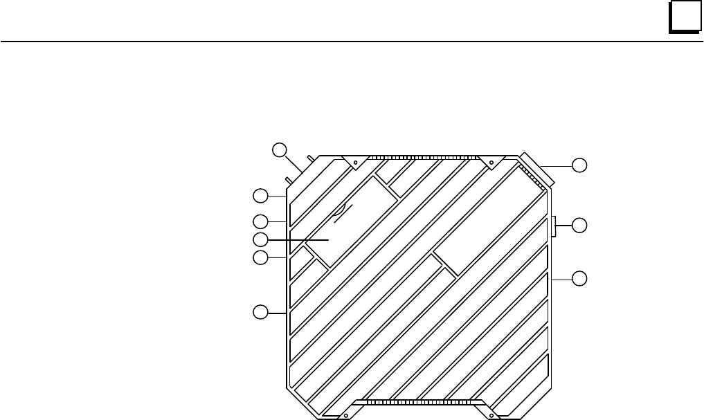
Figure 2 - 2. Genius Panel Controller (C400) Elements/Connections
1
. Display Module Connector (ribbon
cable)
2
. 24 VDC Power Supply Connector
3
. IF0: RS-232 (to PC), labeled 0
4
. Genius Bus Connector
5
. Keyblock Module Connector
6
. Mode Switch - Operating Mode
7
. Cover for Lithium Battery
8
. Device Number Switches
9
. Reset Button