
Appliance Trim Kit User Manual


Table Of Contents
- Chapter 1 Overview
- Chapter 2 C400 Panel Controller Hardware
- General Information
- Genius Panel Controller (C400)
- Specifications
- Overview of Connections and Operational Elements
- VDC Power Supply (item 2, Figure 2-2)
- IF0 - RS-232, Non-isolated (item 3, Figure 2-2)
- Genius Bus Connector, Isolated (item 4, Figure 2-2)
- Mode Switch (item 6, Figure 2-2)
- Device Number Switches (item 8, Figure 2-2)
- Lithium Battery (item 7, Figure 2-2)
- Reset Button (item 9, Figure 2-2)
- Operating the C400 Controller
- Chapter 3 Quick Start
- Calling the Setup Program
- Language Selection
- Installation Menu
- Pull-Down Menus (Main Menu)
- Window Name
- Selection Windows
- Context-Sensitive Help Screens
- Screen Elements
- Connection to a GE Fanuc PLC via Genius
- Internal Connection
- Genius Internal Connection
- Picture 1
- Picture 2
- Picture 3
- Genius Device Connection
- Genius Internal Connection
- Internal Connection
- Picture for a Communications Error
- Picture Binding Overview
- Picture List Organization
- Chapter 4 Configuring Communication with the PLC
- Chapter 5 PCS Connection Editor
- Chapter 6 Demo Project
- Appendix A Cabling Information
- Appendix B Errors/Troubleshooting
- Index
GFK-1115 Chapter 3 Quick Start 3 - 17
3
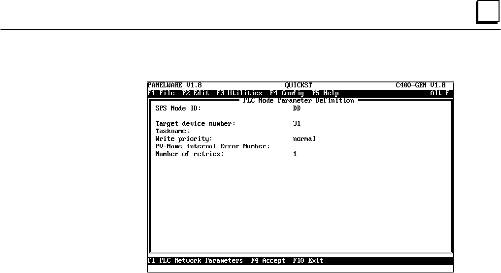
Here, the Target device number, or Genius bus address, of the connection is specified. Enter the
bus address of your GBC (typically bus address 31) in the Target device number field.
No other data needs to be entered into the PLC Node Parameter Definition screen for this
example. Pressing F4 Accept completes the entry