
Appliance Trim Kit User Manual


Table Of Contents
- Chapter 1 Overview
- Chapter 2 C400 Panel Controller Hardware
- General Information
- Genius Panel Controller (C400)
- Specifications
- Overview of Connections and Operational Elements
- VDC Power Supply (item 2, Figure 2-2)
- IF0 - RS-232, Non-isolated (item 3, Figure 2-2)
- Genius Bus Connector, Isolated (item 4, Figure 2-2)
- Mode Switch (item 6, Figure 2-2)
- Device Number Switches (item 8, Figure 2-2)
- Lithium Battery (item 7, Figure 2-2)
- Reset Button (item 9, Figure 2-2)
- Operating the C400 Controller
- Chapter 3 Quick Start
- Calling the Setup Program
- Language Selection
- Installation Menu
- Pull-Down Menus (Main Menu)
- Window Name
- Selection Windows
- Context-Sensitive Help Screens
- Screen Elements
- Connection to a GE Fanuc PLC via Genius
- Internal Connection
- Genius Internal Connection
- Picture 1
- Picture 2
- Picture 3
- Genius Device Connection
- Genius Internal Connection
- Internal Connection
- Picture for a Communications Error
- Picture Binding Overview
- Picture List Organization
- Chapter 4 Configuring Communication with the PLC
- Chapter 5 PCS Connection Editor
- Chapter 6 Demo Project
- Appendix A Cabling Information
- Appendix B Errors/Troubleshooting
- Index
GFK-1115 Chapter 3 Quick Start 3 - 33
3
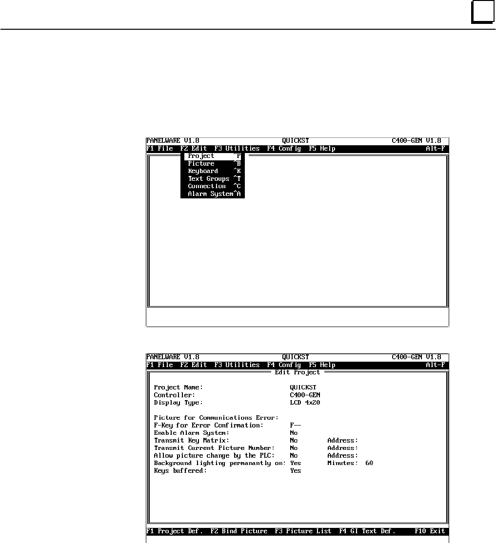
Section 10 Binding Pictures in the Project
The pictures that you have created for this project still have to be bound into the project definition.
To begin the binding process, select the Project option from the F2 Edit pull-down menu or press
Ctrl + P.
The Edit Project window shown below is opened:
The picture binding process for this project consists of the following three steps:
1. Entering the filename of the ERROR picture
2. Binding the three project pictures
3. Organizing the picture directory
These processes are explained in the sections that follow.