
Appliance Trim Kit User Manual


Table Of Contents
- Chapter 1 Overview
- Chapter 2 C400 Panel Controller Hardware
- General Information
- Genius Panel Controller (C400)
- Specifications
- Overview of Connections and Operational Elements
- VDC Power Supply (item 2, Figure 2-2)
- IF0 - RS-232, Non-isolated (item 3, Figure 2-2)
- Genius Bus Connector, Isolated (item 4, Figure 2-2)
- Mode Switch (item 6, Figure 2-2)
- Device Number Switches (item 8, Figure 2-2)
- Lithium Battery (item 7, Figure 2-2)
- Reset Button (item 9, Figure 2-2)
- Operating the C400 Controller
- Chapter 3 Quick Start
- Calling the Setup Program
- Language Selection
- Installation Menu
- Pull-Down Menus (Main Menu)
- Window Name
- Selection Windows
- Context-Sensitive Help Screens
- Screen Elements
- Connection to a GE Fanuc PLC via Genius
- Internal Connection
- Genius Internal Connection
- Picture 1
- Picture 2
- Picture 3
- Genius Device Connection
- Genius Internal Connection
- Internal Connection
- Picture for a Communications Error
- Picture Binding Overview
- Picture List Organization
- Chapter 4 Configuring Communication with the PLC
- Chapter 5 PCS Connection Editor
- Chapter 6 Demo Project
- Appendix A Cabling Information
- Appendix B Errors/Troubleshooting
- Index
GFK-1115 Chapter 4 Configuring Communication with the PLC 4 - 5
4
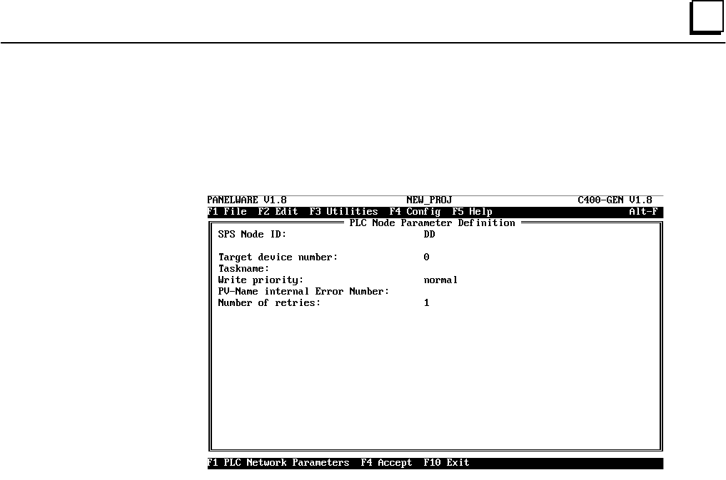
PLC Node Parameter Definitions
Additional information must be supplied for every defined connection except for an Internal or
GENIUS Internal connection. Use the cursor keys to highlight the desired connection, then press
the F4 PLC Node Parameters key to access the PLC Node Parameter Definition window.
Note
In most instances, the default settings indicated in the window will suffice. The
one exception is the Target device number setting, which must be set to match
the Genius bus address of the device represented by the connection. Parameters
indicated by an * must correspond to the configuration of the PLC interface at
the other end.
❏ Target device number*
This is the Genius serial bus address, or device number, of the device represented by the
connection. This value ranges between 0 and 31, inclusive, and must be provided for
every connection.
❏ Taskname*
This parameter must be specified only if you wish to access %P or %L data via a
Series 90-70 GBC. If you do wish to specify it, supply the 1 — 7-character
Taskname of the program running in the 90-70 CPU.