
Appliance Trim Kit User Manual


Table Of Contents
- Chapter 1 Overview
- Chapter 2 C400 Panel Controller Hardware
- General Information
- Genius Panel Controller (C400)
- Specifications
- Overview of Connections and Operational Elements
- VDC Power Supply (item 2, Figure 2-2)
- IF0 - RS-232, Non-isolated (item 3, Figure 2-2)
- Genius Bus Connector, Isolated (item 4, Figure 2-2)
- Mode Switch (item 6, Figure 2-2)
- Device Number Switches (item 8, Figure 2-2)
- Lithium Battery (item 7, Figure 2-2)
- Reset Button (item 9, Figure 2-2)
- Operating the C400 Controller
- Chapter 3 Quick Start
- Calling the Setup Program
- Language Selection
- Installation Menu
- Pull-Down Menus (Main Menu)
- Window Name
- Selection Windows
- Context-Sensitive Help Screens
- Screen Elements
- Connection to a GE Fanuc PLC via Genius
- Internal Connection
- Genius Internal Connection
- Picture 1
- Picture 2
- Picture 3
- Genius Device Connection
- Genius Internal Connection
- Internal Connection
- Picture for a Communications Error
- Picture Binding Overview
- Picture List Organization
- Chapter 4 Configuring Communication with the PLC
- Chapter 5 PCS Connection Editor
- Chapter 6 Demo Project
- Appendix A Cabling Information
- Appendix B Errors/Troubleshooting
- Index
5 - 6 PANELWARE MMI Application Manual for GE Fanuc Genius Protocol - June 1995 GFK-1115
5
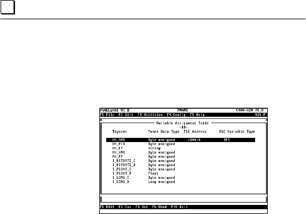
Editing the Variable Assignment Table
The VAT is used to assign absolute PLC addresses to symbolic variables. All connection variables
that are entered as PLC addresses during the project creation are listed in the Variable
Assignment Table.
When you press the F5 VAT key from the connection list, the VAT screen for the selected
connection is displayed. The following screen is an example:
Elements of the VAT
The VAT for any connection consists of the following elements:
■ Tagname: Symbolic name as follows:
- Entered for an input or output field as the PLC address with the ID for this connection.
- Entered for PLC addresses of the alarm system with the ID for this connection (PLC
address for the alarm bit field, global alarm or bypass image).
- Entered for a key command or LED function with the ID for this connection.
- Entered in the project definition screen with the ID for this connection.
■ Panel Data Type: Indicates (automatically) the data type of the field that the variable
uses (e.g., for Output Byte, Byte unsigned). Every field type is assigned a certain Panel
data type that cannot be changed by the user.