
Appliance Trim Kit User Manual


Table Of Contents
- Chapter 1 Overview
- Chapter 2 C400 Panel Controller Hardware
- General Information
- Genius Panel Controller (C400)
- Specifications
- Overview of Connections and Operational Elements
- VDC Power Supply (item 2, Figure 2-2)
- IF0 - RS-232, Non-isolated (item 3, Figure 2-2)
- Genius Bus Connector, Isolated (item 4, Figure 2-2)
- Mode Switch (item 6, Figure 2-2)
- Device Number Switches (item 8, Figure 2-2)
- Lithium Battery (item 7, Figure 2-2)
- Reset Button (item 9, Figure 2-2)
- Operating the C400 Controller
- Chapter 3 Quick Start
- Calling the Setup Program
- Language Selection
- Installation Menu
- Pull-Down Menus (Main Menu)
- Window Name
- Selection Windows
- Context-Sensitive Help Screens
- Screen Elements
- Connection to a GE Fanuc PLC via Genius
- Internal Connection
- Genius Internal Connection
- Picture 1
- Picture 2
- Picture 3
- Genius Device Connection
- Genius Internal Connection
- Internal Connection
- Picture for a Communications Error
- Picture Binding Overview
- Picture List Organization
- Chapter 4 Configuring Communication with the PLC
- Chapter 5 PCS Connection Editor
- Chapter 6 Demo Project
- Appendix A Cabling Information
- Appendix B Errors/Troubleshooting
- Index
GFK-1115 Chapter 6 Demo Project 6 - 3
6
Section 2 Required Hardware
The following PANELWARE hardware components are required for the demo project (see the
PANELWARE™ Hardware Installation User’s Manual–GFK-0848):
❏ 1 - C400 Panel Controller
❏ 1 - 8 x 40 LCD Display Module
❏ 1 - 12+4 key Keyblock Module
❏ 1 - 16 key Keyblock Module
❏ 1 - connection cable between the PC and the Panel
❏ 1 - connection cable between the Panel and the PLC (see Appendix A)
Assemble these modules according to the instructions in the PANELWARE™ Hardware
Installation User’s Manual (GFK-0848). Ensure that the 12+4 Keyblock module is the first
Keyblock module that is attached directly to the Panel Controller.
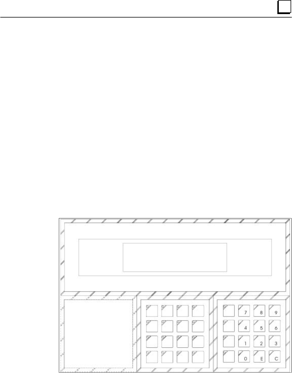
Note
The numeric Keyblock module shown throughout the following sections may not
look like yours, which may not have the E and C keys. Instead, the E key
(ENTER) may be the ↵↵ symbol and the C key (CLEAR) may be the ← symbol.
The assembled Panel should look like the following figure: