Monogram.
Introduction Your new Monogram cooktop makes an eloquent statement of style, convenience and kitchen planning flexibility. Whether you chose it for its purity of design, assiduous attention to detail-or for both of these reasons—you’ll find that your Monogram cooktop’s superior blend of form and function will delight you for years to come. The ZEW and ZGW Monogram cooktops were designed to provide the flexibility to blend in with your kitchen cabinetry.
Before using your cooktop system, read this guide carefully. It is intended to help you operate and maintain your new cooktop components properly. Keep it handy for answers to your questions. If you don’t understand something or need more help, write (include your phone number): Consumer Affairs GE Appliances Appliance Park Louisville, KY 40225 Write down the model and serial numbers. You’ll find them on a label on the bottom of each component.
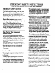
IMPORT~ SAFETY INSTRUCTIONS Read all instructions before using this appliance. IMPORTM SAFETY NOTICE ● . The California Safe Drinking Water and Toxic Enforcement Act requires the Governor of California to publish a list of substances known to the state to cause cancer, birth defects or other reproductive hand requires businesses to warn customers of potential exposure to such substances.
not s~re fl~mable matefials in an oven or near the cooktop system components. Do not stem or me comb~tible materi~s, gasoline or other flammable vapors and liquids in the vicinity of this or any other gas or electric appliance. . Do not let COOking grease or other flammable materials accumulate in or near the cooktop system components. ● Do Potentially hot surfaces include the grill grates, griddle and all components with electric cooking elements or gas burners and grates. ● .
IMPORT~ SAFETY INSTRUCTIONS (continued) ● ● Use little fat for effective shallow or deep-fat frying. Filling the pan too fill of fat can cause spillovers when food is added. . After cleaning, use a dry cloth or paper towel to remove all Cook Top Cleaning Creme residue. . Read and follow all instruction and warnings on Cook Top Cleaning Creme labels. If a combination of oils or fats will be used in frying, stir together before heating, or as fats ● melt slowly. .
Cleaning ● ● ● ● ● Do not clean the cooktop system with flammable or volatile cleaning fluids. See the Careand Cleaning section. Do not clean any part of the cooktop system when the appliance is in use If you are using an overhead exhaust hood, keep its grease falters clean to maintain good venting and to avoid grease fires. Clean only parts listed in this Use and Care Guida Clean the cooktop with caution.
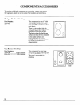
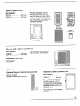
COMPONENTS/ACCESSORIES To purchase additional components or accessories, contact your nearest GE Appliances dealer or service center. Part numbers are listed below. Halogen/Radiant Cooktop Part Number: ZEW145 The component has one 8“ 1800 watt halogen surface unit (rear) and a 6“ 1200 watt radiant surface unit (front). There is a hot surface light for each surface unit that indicates the condition of the glass surface.
. Electric Updraft Grill Part Numbers: ZEW154 ..........................208 volts ZEW155 ..........................240 volts With this component, you can charbroil meat indoors all year long. Fat drains away and collects in ajar attached below the grease well. The element is divided so the front and back sections can be controlled separately. .’~ Grill Element Drip Pan Grill Grate I Grease Collector Jar 151 . Grease Well Electric Grill with Downdraft Vent Part Numbers: ZEW164 ........................
HOW DOES THISCOOKTOP COMPARE TO YOUR OLD ONE? Your new cooktop may have one of several types of cooking surface units. You will notice some differences when you use each one. The best types of cookware to use, plus heat-up and cool-down times, depend upon the type of burner or surface unit you have. The following chart will help you to understand the differences between your new cooktop and any other type of cooktop you may have used in the past.
HALOGEN/RADIANT SURFACE UNIT CONTROLS Halogen Surface Unit The controls selected for the halogenhadiant component will give you a full range of heat settings for cooking. The control knobs must be pushed down to turn from the off (0) position. When the control knobs are in any position other than off(0), they may be turned without pushing down. You may notice that the knob that operates the halogen surface unit is slightly harder to turn than the knob for the radiant surface unit.
GAS BURNER CONTROLS See the Gas Burner Component section. The gas burnercontrols must tum counterclockwise to the LITE position to ignite the burner. Once the burner is ignited, turn the control knob counterclockwise to adjust the flame lower. A sparking sound caused by the igniter is normal until ignition occurs. The burners will relight at any setting.
HALOGEN/RADIANT COMPONENT General Information About Halogen/Radiant Surface Units The halogen/radiant cooktop features heating units beneath a smooth glass ceramic surface. The surface units are shown by outlines on the glass. Before you use the cooktop for the first time, clean it with Cook Top Cleaning Creme. This helps protect the top and makes clean-up easier. NOTE: A slight odor is normal when a new cooktop is used for the first time.
HALOGEN/R.ADIA.NT COMPONENT (continued) Vpes of Cookware The following information will help you choose cookware which will give good performance. Stainless Steel: highly recommended Especially good with a sandwich clad bottom. The sandwich bottom combines the benefits of stainless steel (appearance, durability and stability) with the advantages of aluminum or copper (heat conduction, even heat distribution). Aluminum: heavy weight recommended Good conductivity.
● Place only @ pans on the surface units. Do not place lids on the surface units, particularly wet lids. s We recommend that you use only a flat-bottomed wok. They are available at your local retail store. The bottom of the wok should have the same diameter as the surface unit to insure proper contact. ● ● Do not use woks that have support rings. This type of wok will not heat on halogenhadiant surface units.
HOME CA.NNINGTIPS Canning cannot be done on the grill or griddle components. Observe the Following Points in Canning 1. Be sure the canner fits over the center of the surface unit. If your range or its location does not aIlow the canner to be centered on the surface unit, use smaller diameter pots for good canning results. 2. On the glass cooktop, flat bottomed canners must be used.
USINGYOUR GAS BURNER COMPONENT The ZGW124 and ZGW125 gas cooktops are not convertible to LP gas. They are designed to operate on natural gas only. This component has one large 1O,5OO-BTUburner and one smaller 6,000-BTU burner. When a downdraft vent is used next to a gas component, food will cook faster if you use a low vent setting and keep the pan covered (if recipe allows).
USING YOUR GAS BURNER COMPONENT (continued) How to Select Flame Size Watch the flame, not the knob, as you reduce heat. The flame size on a gas burner should match the cookware you are using. FOR SAFE HANDLING OF COOKWARE, NEVER LET THE FLAME EXTEND UP THE SIDES OF THE COOKWARE. Any flame larger than the bottom of the cookware is wasted heat and only serves to heat the handle. Cookware Medium-weight cookware is recommended because it heats quickly and evenly.
Burner Assembly CAUTION: DO NOT OPERATE THE BURNER WITHOUT ALL BURNER PARTS CORRECTLY IN PLACE. The burner assemblies should be washed regularly and, of course, afier spillovers. Turn all the controls off and wait until all component parts are cool before removing burner parts. See the Care and Cleaning section. The electrode of the spark igniter is exposed when the top of the burner is removed. Contact with an exposed igniter while a burner is being turned on will cause a slight electrical shock.
GRILL COMPONENT (continued) What to do if a Flame-Up Occurs To control flame-ups, set heat setting at LO, rather than off (0). If you have a bad flame-up and there is danger of the fire spreading, take the following steps immediately: 1. Turn the grill controls to off (0), and turn the downdraft vent control to HI. If you are using an overhead updraft vent hood, turn it off until the flame-up stops. NOTE: c NEVER USE WATER ON A GREASE FIRE. Water will spread the flames.
Grill Tips . Do not leave grill unattended while it is in use. “ Use the ~gill ONLY with the downdraft vent blower on HI to carry away smoke and fumes. . Remove accumulated grease from the nonremovable grease well after each use to lessen smoking and odors. Be sure opening to grease tube is clean. Grease buildup can become a fire hazard. Make sure the removable grease collector jar and drip pan are clean and in place before using the grill.
GRILL COOKING GUIDE Do not leave the cooktop unattended during . Before cooking steaks, slash the fat around “preheat>>(knobs turned to ‘W.P7)or anytime the the edges to prevent curling of the meat. . Suggested cooking times should be used only as a guide, since variables in food can change the cooking times. . Foods should be turned over and rearranged as needed. knobs are turned to “HI” with food on the grill or griddle. Most foods will be grilled on the HI setting.
GRIDDLE ACCESSORY See the Griddle Cooking Guide. Your non-stick coated griddle provides an extralarge cooking surface for meats, pancakes or other foods usually prepared in a frying pan or electric skillet. You can also use the griddle as a warming tray by using a low-heat setting. me griddle has its own integal cooking element- The control marked GRIDDLE changes the temperature over the entire surface.
GRIDDLE ACCESSORY (continued) Griddle Tips Condition or “season” griddle before first-time use. Most griddled foods are those that require cooking on a preheated surface. The ~tiddle surface may be Oreased lightly before adding food. Preheat the & griddle 5 minutes at HI heat setting, unless otherwise indicated in the Griddle Cooking Guide, then switch to the recommended cook setting. . Foods which are high in natural fat, such as bacon or sausage, may be started on a cold ~tiddle.
GRIDDLE COOKING GUIDE Do not leave the cooktop unattended during “preheat” (knobs turned to “HI”) or anytime the knobs are turned to “HI” with food on the griil or griddle. Most foods will be cooked on the griddle on the HI setting. Some foods need to be cooked at lower settings. . Avoid using metal utensils with sharp points or rough or sharp edges which may damage the nonstick coated griddle surface. Do not cut foods on the griddle.
CARE AND CLEANING Proper care and cleaning are important so your Component Cooktop System will give you efficient and satisfactory service. Follow these directions carefully to help assure safe and proper maintenance. BE SURE ELECTRICAL POWER IS OFF BEFORE CLEANING ANY COMPONENTS. Care of Components Some of the components must be cured or preconditioned before using them for the first time. Components and accessories should be cleaned after each use.
Halogen/Radiant Cooktop—G1ass Ceramic Cooktop Cleaning Cleaning of glass ceramic cooktops is different from cleaning a standard porcelain finish. To maintain and protect the surface of your new glass ceramic cooktop follow these basic steps. Before you use the cooktop for the first time, clean it with Cook Top Cleaning Creme. This helps protect the top and makes clean-up easier. DAILY CLEANING: Use only Cook Top Cleaning Creme on Glass Ceramic. For normal, light soil: 1.
CARE AND CLEANING (continued) Gas Burner Assembly The burner assemblies should be washed regularly and after spillovers. Turn all control knobs to the off (0) position before removing burner parts and the drip pan. CAUTION: DO NOT OPERATE THE BURNER WITHOUT ALL BURNER PARTS CORRECTLY IN PLACE. The electrode of the spark igniter is exposed when the burner cap is removed. Contact with an exposed igniter while a burner is being turned on will cause a slight electrical shock.
Grill Component Clean the grill component after every use. Do not put the element into water. It cleans itself when heated during normal use. To remove any charred soil, clean with a dry, stiff brush when the element is cool. Never use steel wool or metal scouring pads because they may damage the outer casing of the element. Wash the grill grate in the sink in soap and water. The grate may be soaked in a solution of dishwasher detergent and hot water. Use a non-metal scouring pad if necessary.
CARE AND CLEANING (continued) How to Clean the Vent System The downdraft vent grille and filter should be cleaned frequently— after every use is best. Before cleaning the vent system, be sure exhaust blower is shut off. To remove parts for cleaning: 1. Lift off the vent ~tille. 2. Rotate the latch away from the solid edge of the filter to free the filter. Pull out the aluminum grease filter. How to Clean the Vent Grille To clean the vent ~tille, remove it from the cooktop by lifting it up.
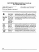
THE PROBLEM SOL~R PROBLEM POSSIBLE CAUSE COMPONENTS ARE NOT FUNCTIONING PROPERLY Difficulty may be in the main distribution panel of your house caused by a blown circuit fuse, a tripped circuit breaker, the main fise or the main circuit breaker, depending on the nature of the power supply. If a circuit breaker is involved, reset it. If the control box uses fuses, the circuit fuse (a cartridge-type) should be changed, BUT ONLY BY SOMEONE FAMILIAR WITH ELECTRICAL CIRCUITS.
THE PROBLEM SOLWR (continued) PROBLEM HOT SUGAR MIXTURES/ PLASTIC MELTED TO THE HALOGEN/RADIANT SURFACE CONTROL KNOB WILL NOT TURN SPARKING SOUND OF SPARK IGNITER PERSISTS AFTER BURNER LIGHTS SP~KING SOUND PERSIST$ AIWER BURNER IS OFF BURNERS DO NOT LIGHT POSSIBLE ● ● CAUSE Turn the surface unit to LO, wipe the hot cooktop with several dry paper towels. Use a razor scraper held at a 30° angle to the cooktop to scrape the hot spill to a cool area outside the surface unit. Let the cooktop COO1.
Table of Contents Installation Instructions .......................................................................................... 34 Important Safety Instructions ........................................................................... 34 Installations not allowed .................................................................................... 34 Warnings ............................................................................................................... 34 Tools Required ..........
Installation Instructions Before you begin – Read these instructions completely IMPORTANT – Save these instructions IMPORTANT - OBSERVE ALL GOVERNING - Keep these instructions Note - This appliance Important safety instructions must be properly use. CODES AND ORDINANCES. A1ote to Installer -Be sure to leave these instructions Note to Consumer and carefully. for local inspector’s with the Consumer. with your Use and Care Book for future reference. grounded.
Design Information Component Mode& available Cooking Surfaces ZEW745T Halogen and Radian? Cooktop Component (240 volt and208 volt) Diagram 35.t ZGW724EN Gas Cooktop Component. Right Hand Controls ZG W125EN Gas Cooktop Component, Left Hand Controls ,.” . . . ZJr ‘7 ZEW154N Updrafi Grill Cooktop Component (208 voh) ZEW155N Updraft Grill Cooktop Component (240 volt) I Diagram 35.3 . .,.. I Diagram 35.
Design Information Component Cooking Surfaces Installation accesson”es End Cap “ Joiner strips and end caps provide a finished any modular cooking arrangement. Downdraft Joiner Downdraft End Cap .lomer look to (Shipped with product.) Dimensions ---and clearances ZG W124EN Gas Cooktoo Comoonent Right Hand Controls ~ote; Gas units are not convertible to liquid propane gas operation. “T*> I I Dtagram 36.3 Includes . 1/2” the following: inlet pipe .
Dimensions and clearances ZEW145T Halogen and Radiant Cooktop Component II (continued) -+-” ● 3P I ●Allow an additional 1- depth for clearance of flexible conduit D/agram371 Includes the following: 44” flexible conduit One joiner strip Two sets clamping 240 Volt and 208 Volt.
Design Information Component Dimensions and clearances ZEWI 75N* Downdraft Vent Cooktop Component Cooking Surfaces I (continued) 19-7/8” I h-l *115Volt AC IJagram 381 . Attaches to gas or Halogen/Radiant components One downdraft (not updraft grill) - Blower can be relocated Includes endcap Two vent housing to opposite side of housing support braces the following: . 48” flexible conduit “ Two downdraftjoiner strips ZEW165N* ZEW164M** Downdraft Grill Cooktop Component .
Installation o@ons The Monogram Component Cooktop ultimate in design and cooking cooktops and accessories, technologies System offers the flexibility, providing with modular a variety of cooking to meet the needs of the most discerning cook. can be installed in many orientations in the countertop. within the cooking – Multiple as permitted .
Design Information Component Cooking Surfaces Preparing Step for . Installation I 13” t~ Max. II d One or 30” Min. A ~ ●*1” Min. 36” ●1” Min to Front Edge to Wall Information ● A ● .---— .“ c Refer to Cabinet~ appropriate planning and necessary * Gas requires 2“ min. to side wall . When installed, on clearances when the following directly above cooktops when is used above cooking -1” from side of cooktop surface: – Use cabinets no more than 13“ deep.
Cabinetry Component 2 Step Preparing the Counter-t@ Cooking Surfaces Tools and materials required: ● Saw ● Measuring ● Carpenter’s tape square cutout information 4“ Mmlmum between Cutouts 4“ Minimum between Cutouts 4“ n’r Da Front to Back Orientation Uiagram47. . Side to Side Orientation 7 Llagram41 “ Minimum clearance is 4“ between cooktops 2 in separate cutouts. “ The 4“ minimum multiple clearances component do not apply when cooktops are installed in one cutout.
Cabinetry Component 2 Prepating Step If multiple components will be attached together, determine dimension Cooking Surfaces A from the following: the Count&op (continued) Unit 1 1o ‘, El 0 cutout information: multiple component units Unit 2 . . . ‘:\ Lnit 3 Radiant Unit5 Unit 4 Radiant 29 -3/4” 0 u RH Gas o El .,., ., >. El Radiant El ;:! ..: .. RH Gas ~‘ -; D././.. . Updraft 30-5/8” Grill RH Gas ----: ~. D Downdraft .o:. :. H o \. \..
2 Step Preparing the Counter-top (continued) cutout information: altmate arrangements If your configuration is not shown in the previous charts, use the following chart to calculate your cutout size. For each of the following dimensions components, add the given.
Cabinetry Component 2 Step Prepating the Countertc@ Example.
Ductwork Component 3 Step Cooking Surfaces Preparing JorDuctwork Ventingojbtions D Through Floor Between Joists Through Floor & Under Jotsts Diagram 451 Direct to Outdoors to Roof fhgram 45.2 Because the .Monogram Component Cooktop has a variety of cooking technologies adaptable wide array of countertop configurations, cooktops vent units maybe and downdraft System to a multiple . Plan route for venting exhaust to outdoors. .
Ductwork Component 4 Step Installing the Ductwork Ductwork arrangements Tools and materials ! required: ● Downdraft Hole saw s Measuring Cooking Surfaces $ Downdraft 1 tape s Framing square Blower Mounted left, Oriented Rear “ Using countertop Blower Mounted Right, Oriented Rear. layout lines as reference, project center line of vent component vertically onto rear and floor of cabinet.
4 Step Installing the Ductwork (continued) II Optional duct arrangement under concreteslab Diagram 471 “ The illustration above is applicable vented cooktop installation “ Use recommended only to downdraft into slab construction. wall caps with damper. Laundry type wall caps should never be used. - Ductwork must be vented to the outside. . 6“ PVC duct should be used when installing under a concrete Note: Localbuilding code must slab. .
Ductwork Component 4 Step Use copies of this form to Installing the Ductwork compute (continued) permissible Duct fittings Cooking Total maximum lengths for Duct Piece Dimensions duct runs to outdoors. equivalent Flexible m / flexible (per foot straight length) 3-1/4” x 1o“ (per foot straight length) 90° elbow Q 15 ft. The ~,1 metal duct should be straight and smooth and extended Length 6“ length values in the table be doubled.
Gas and Electrical Supply Component 5 Step Gas supply location Cooking Surfaces Tools and materials required: ● Pipe and fittings ● Manual gas-line shut-off as required. ge valve. Monogram component updraft or downdraft gas cooktops venting) on natural gas at 4“ water column supplied (used with either are designed pressure. to operate Cooktop with 3/8” NPT female gas connection rear corner for right hand control unit and left rear corner for left hand control unit. .
Installation Component 7 Installation Step Tools and materials ● required: ●5/16° nutdriver ● Measuring ● Pencil tape 1/4” nutdriver ● 7/16“ and 5/16” socket and ● ratchet wrench bit Halogm/Radiant I$&’~eSive gasket Strip socket cookt+, updra~ Philiips screwdriver (supplied) grz”lland If installing a downdraft grill cooktop and blower that doumdrafip”ll requires reorientation and/or relocation, refer to ● “ReOtient Gas cookt~ Blowern and “Relocate Tools and materials ● required: ●
7 Installation Step (continued) Jo~n@ multiple cooktops Remove — These Nuts H Cooktop Joiner Strip D/agram57 7 If available, an assisrant can ease the installation process. “ Using a large, solid work surface, lay cooktops upside “ Place flanged nuts in end of 5/16“ under counter, nutdriver. From start nuts on studs and tighten. down on soft, clean towel. . Remove endcaps on sides to be joined three nuts with 5/ 16“ nutdriver. . Attach joiner by removing Discard nuts.
Installation Component 7 Cooking Surfaces Installation Step (continued) Jo~nW cooktq ~“ downdrafi vent Note: To prevent knobs being scratched, knobs must be removed from component before it is turned upside down. D/agram521 . Remove all grates, knobs, burner caps, drip pans, etc. “ Lay cooktop upside down on soft, clean towel on a large work surface. s Remove endcap on side ofcooktop to bejoined by %) removing three nuts with 5/ 16“ nutdnver. Discard nuts.
7 Installation Step (continued) Jonung additional cooktopto downdrafi vent or to downdrafi~“11 42) ~ Front of Countertop I Diagram 53.1 “ Remove endcap on side of next cooktop “ Pre-tap holes in downdraft joiner driving supplied backing joining Securing cooktop(s)to countertop screws through out before installation. to be joined. and endcaps “ Place cooktop using Phillips screwdriver holes and then This will facilitate the strip to cooktop.
Installation Component h Step Installation If necessary, (continued) direction, / the blower or relocated maybe rotated to opposite 90° k either side of vent housing. “ Remove filter from vent housing with Phillips screwdriver. Reorient blower D/agram 541 o Remove blower side plate (four nuts) with 5/1 6“ nutdriver and set aside. Diagram S42 . Remove blower (four nuts) with 7/16“ socket wrench from inside vent housing and set aside.
7 Installation Step (continued) Relocate blowe?- Dfagram 551 After duct location relocate is determined, blower to opposite “ Follow previous it may be necessary to side of vent housing. instructions to remove blower side plate and blower. o Remove filter guide from inside vent housing with Phillips screwdriver. “ Relocate filter guide to opposite . Replace Relocate side of vent housing. screws and tighten with Phillips screwdriver. blower to opposite outlet oriented .
Installation Component Step 9 Connect electn”cal “ Halogen/Radiant, downdraft updraft grill, downdraft Cooking Surfaces grill and vent component: 3-Conductor Branch Circu]t Branch Circuit Cooktop Red Red White or Gray White +120V AC Neutral Bare or Green Black Black -120VAC .3-Conductor Branch Circuit: J \ Lhagram 56.1 “ Connect red lead to branch “ Connect black lead to branch circuit black lead. o Connect cooktop circuit red lead.
10 Assemble Step Electric Components: burners, Push in and turn each knob to high position. ctick sure each heating element Make heats up. < W ?Bumer Grate ignition Gas Components: (Electrical connections should be complete.) I “ Plug power cord into outlet. “ Assemble “ Check for proper ignition: - Push in one control knob and turn 90° to HIGH position.
Remote Control Kit Installation Component Pub. No. 3-AO1O optionfor downdrafivent or downdrafi ~“11component Cooking Surfaces Tools and materials required: . Remote Control Kit ● 1-5/8” hole saw ● 1/4” drill bit . Drill cPhillips ● \ /c1 screwdriver 9/16“ deepwell socket and ratchet wrench s Pencil ● 2 Phillips head screws Downdraft Grate Knob/Escutcheon Uagram w 1 Control Box —. I m 1-5/8” Min.
Mounting downdrafi blowercontrol Countertop location: (continued) fI/ote: Control box flange faces toward cooktop. Diagram 59.1 “ Center 1/4” hole to left of 1-5/8” hole. (Reverse if cooktop control box is on other side of cooktop. ) Cabinet front location, centered on downdraft vent: Note; Control box flange faces up. Diagram 59.
Remote Control Component Kit Installation Cooking Surfaces Accessorykit installation (continued) Front of Countertop D/agram 601 “ Remove grate and knobs. “ Detach control downdraft box from front of downdraft grill by removing Phillips screwdriver, deepwell Confirm vent or the two screws with a and the shaft nut with a 9/ 16“ socket. remote control location cable to assure sufficient by initial routing of length and bend capability.
NOTES 61
With the purchase of your new Monogram need information or assistance appliance, receive the assurance that ifyou ever born GE, we’ll be there. All you have to do is call—toll-free! I!Home RepairSewice 801WE#ARES(801M32-2737) AGE consumer service professional will provide expert repair service, scheduled at a time that’s convenient for you. Many GE Consumer Service company~perated locations offer you service today or tomorrow, or at your convenience (7:00 a.m. to 7:00 p.m. weekdays, 9:00 a.m.
YOUR MONOGRAM COOKTOP WARRANTY WHAT IS COVERED Staple sales slip or cancelled check here. Proof of original purchase date is needed to obtain service under warranty. FULL ONE-YEAR WARRANTY For one year from date of original purchase, we will provide, free of charge, parts and setvice labor in your home to repair or replace my part of the cooktop that fails because of a manufacturing defect.
-. Pub. S(). 49-8487 Part So.