GE Monogram® Installation Instructions 36" Downdraft Gas Cooktops Models ZGU365
Before you begin—Read these instructions completely and carefully. IMPORTANT: Save these instructions for local inspector’s use. IMPORTANT: OBSERVE ALL GOVERNING CODES AND ORDINANCES. NOTE TO INSTALLER: Be sure to leave these instructions with the Consumer. NOTE TO CONSUMER: Keep these instructions with your Owners Manual for future reference. CAUTION WARNING This appliance must be properly grounded. See “Power Supply”, page 8. ATTENTION Cet appareil doit être correctement mis à la terre.
Design Information G a s Downdraf t Cooktop Models Available ZGU365 36" gas downdraft cooktops Accessories These gas downdraft cooktops are equipped with an vent system which can be retracted when not in use. • JXBA56WW, white or JXBA56BB, black motor and blower assembly is required for both models. Be sure to order the color that matches the cooktop. These models are shipped for natural gas operation. They can be converted to liquid propane. (Order JXLP56 conversion kit.
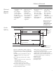
Design Information G a s Downdraf t Cooktop Advance Planning The combined installation of a downdraft vent and cooktop require careful consideration. Countertop Requirements: The countertop must have a deep flat surface to accommodate the cooktop and the vent. Countertops with a rolled front edge and backsplash may not provide the flat surface area required. 4 Base Cabinet Requirements: This installation requires a 24" min. deep cabinet base. The cabinet must be at least 36" wide.
Cabinetry/Ductwork G a s Downdraf t Cooktop Tools and Materials Required • Self-adhesive gasket (supplied) • Two clamping brackets and screws (supplied) • Gas pressure regulator (supplied) • Large flat-blade screwdriver • Saw • Carpenter’s square • Pipe wrench • Manual gas line shut-off valve • 3/4" NPT x 3/4" I.D. or 1/2" NPT x 1/2" I.D. flare union adaptor for connection to supply line •Duct work to suit the installation • 1/2" NPT x 3/4" I.D. or 1/2" I.D.
Ductwork G a s Downdraf t Cooktop Venting Options • The downdraft vent is shipped with the discharge outlet pointing straight down and can be changed to the left or right side. • The blower outlet is sized for 3-1/2" x 10" and can be transitioned to 6" round. Side to side adjustments: The entire blower mounting plate can be adjusted 3-1/2" to the left or right. This will help to align vent discharge to house ductwork.
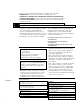
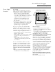
Ductwork G a s Downdraf t Cooktop Duct Fittings Use this form to compute maximum permissible lengths for duct runs to outdoors. Note: Do not exceed maximum permissible equivalent lengths! Flexible ducting: If flexible metal ducting is used, all the equivalent feet values in the table should be doubled. The flexible metal duct should be straight and smooth and extended as much as possible. Do NOT use flexible plastic ducting.
Gas and Electrical Supply G a s Downdraf t Cooktop Power Supply Locations Gas supply: These cooktops are designed to operate on natural gas at 4" of water column pressure or on LP gas at 10" of water column pressure. –These cooktops are shipped from the factory set for natural gas. If you decide to use this cooktop with LP gas, conversion adjustments must be made by a service technician or other qualified person. JXLP56 conversion kit is required for LP operation.
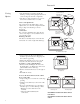
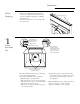
Installation G a s Downdraf t Cooktop Remove Packaging 1 • Remove the shipping materials and the carton, set carton aside. The carton can be used as a pad when changing or adjusting vent direction. • Remove the plastic ties on both ends at the top of the vent.
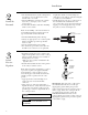
Installation G a s Downdraf t Cooktop 2 Step Install the Ductwork • The downdraft blower system is designed for use with 3-1/4" x 10" ductwork. It can be transitioned to 6" round. • Ductwork MUST be vented to the outside – never into a crawl space, attic or other enclosed space. • 6" PVC duct should be used when installing under a concrete slab. length when bends or various fittings are used. Refer to the table of equivalent lengths to calculate your installation.
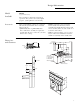
Installation G a s Downdraf t Cooktop 4 Step Install the Cooktop Note: If the cooktop is installed into a 36" base cabinet, the pressure regulator MUST BE installed to the bottom of the cooktop before the cooktop is placed into the cabinet. • Remove packaging from the cooktop. • To insure a good fit, position the cooktop over the cutout opening and carefully lower into place. Check edges all the way around to be sure all cutout edges are concealed and there are no gaps.
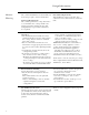
Installation G a s Downdraf t C ooktop 5 Step Electrical Connections • Connect the 3-pin plastic plug from the blower/motor assembly to the 3-pin plastic socket on the underside of the vent, next to the conduit. • Slide the metal cover over the connection and secure with screws. • Connect the 6-pin plastic plug from the downdraft assembly to the 6-pin plastic socket on the underside of the cooktop, next Service to the power cord.
Installation G a s Downdraf t Cooktop 8 Step Install Filters Check Operation of Downdraft To raise the vent, turn the VENT knob to RAISE/LOWER. • Hold the knob until the vent begins to raise. – The vent will automatically stop when it is fully extended. • Tip filter into the opening and pull straight down so that the filter rests on slides. • Slide the filter to the right side. • Tip the other filter into the opening and pull straight down. • To turn the fan on, turn the FAN knob to HIGH.
JXRB57 Kit For Indoor Remote Blower Locations Tools and Materials required: • Pencil • Measuring tape • Drill with appropriate bits • Nut driver • Junction box • Wire nuts • Safety glasses • 3-1/4" x 10" to 6" round transition. • 3-1/4 x 10" duct, (or 6" round) sufficient length to reach the outdoor wall cap or roof cap. • Electrical cable and connectors, sufficient length to connect the downdraft vent to the remote blower location. 14-guage min. is recommended, must conform to local codes.
JXRB57 Kit For Indoor Remote Blower Locations 1 Step (continued) • Remove the 4 nuts holding the blower to the mounting plate. One nut is hidden inside the outlet. Remove blower. • Remove the blower mounting plate. • Remove 2 screws along the bottom of the blower box which are visible once blower plate is removed. • Carefully, turn the unit over to access the back side. • Remove 4 screws along the top of the blower box. • Turn unit over and remove the 4 screws along the top. • Remove the blower box.
JXRB57 Kit For Indoor Remote Blower Locations 3 Step Downdraft Connect Ductwork Duct Adapter Outlet Cover • The downdraft plenum can discharge from either the right or left side. Select the side that provides the best alignment to ductwork extending to the blower assembly below. – For a left side discharge, install the outlet plate to the bottom of the plenum on the left side. Install the cover plate to the bottom of the right side. Reverse plates for a right side discharge. .
JXBC57 Kit For Outdoor Remote Blower Locations Materials Required (not supplied) • Approved liquid tight service connections for use between the wire compartment on the base and inside the structure. • 7 wire nuts or other approved connectors. • Six 5/16" dia. fasteners compatible with the type of material the base is being fastened to. • 3-1/4" x 10" to 6" round transition. • 3-1/4 x 10" duct, (or 6" round) sufficient length to reach the outdoor installation location.
JXBC57 Kit For Outdoor Remote Blower Locations 2 Step Mark Mounting Location • The base is designed to be mounted to studs on 16" centers. Use the dimensions shown to determine the location of the ducting and wiring through the wall. – Or Place the base against the exterior wall and mark the 6 mounting locations, the 6" duct location and the hole for the wiring. Use pencil or chalk. • The bottom of the base assembly must be 10" min. above the ground.
JXBC57 Kit For Outdoor Remote Blower Locations 3 Step (continued) • Remove the 4 nuts holding the blower to the mounting plate. One nut is hidden inside the outlet. Remove blower. • Remove the blower mounting plate. • Remove 2 screws along the bottom of the blower box which are visible once blower plate is removed. • Carefully, turn the unit over to access the back side. • Remove 4 screws along the top of the blower box. • Turn the unit over and remove the 4 screws along the top.
JXBC57 Kit For Outdoor Remote Blower Locations 5 Step Connect Electrical 6 Step • Use electrical cable and connectors that conform to local codes (14 gauge min. is recommended). Use a length to reach between the vent and the blower/motor location. • Attach the wire box removed from the blower conduit to the end of new wiaring. • Use wire nuts to secure the wire to the 3" remaining wires with plug. • Insert the plug into the mating plug on the vent. • Reinstall wire box with original screws.
Notes 21
Notes 22
Notes 23
NOTE: While performing installations described in this book, safety glasses or goggles should be worn. To obtain specific information concerning any Monogram product or service, call GE Answer Center® consumer information service at 800.626.2000—any time, day or night. For Monogram local service in your area, call 1-800-444-1845. ® Monogram. General Electric Company Louisville, KY 40225 NOTE: Product improvement is a continuing endeavor at General Electric.