Chimney Vent Hoods GEAppliances.com Safety Instructions . . . . . . . . 2, 3 Operating Instructions Light Controls . . . . . . . . . . . . . . . . . . . . 4 Vent Controls . . . . . . . . . . . . . . . . . . . . 4 Owner’s Manual and Installation Instructions PV970 PV976 Care and Cleaning Grease Filters . . . . . . . . . . . . . . . . . . . . 5 Hood Lights . . . . . . . . . . . . . . . . . . . . . . 6 Stainless Steel Surfaces . . . . . . . . . . 6 Installation Instructions Installation Preparation. . .
IMPORTANT SAFETY INFORMATION. READ ALL INSTRUCTIONS BEFORE USING. SAFETY PRECAUTIONS WARNING – TO REDUCE THE RISK OF FIRE, ELECTRIC SHOCK OR INJURY TO PERSONS, OBSERVE THE FOLLOWING: A. Use this unit only in the manner intended by the manufacturer. If you have questions, contact the manufacturer. B. Before servicing or cleaning unit, switch power off at service panel and lock the service disconnecting means to prevent power from being switched on accidentally.
GEAppliances.com SAFETY PRECAUTIONS WARNING – TO REDUCE THE RISK OF A RANGE TOP GREASE FIRE: A. Never leave surface units unattended at high settings. Boil overs cause smoking and greasy spillovers that may ignite. Heat oils slowly on low or medium settings. B. Always turn hood ON when cooking on high heat or when flambéing food (i.e. Crepes Suzette, Cherries Jubilee, Peppercorn Beef Flambé). C. Clean ventilating fans frequently. Grease should not be allowed to accumulate on fan or filter. D.
Using the hood controls. MEMORY/OFF. 7R VHW WKH PHPRU\ A. Press the MEMORY/OFF button. B. Set your desired fan and light settings. C. Press the MEMORY/OFF button again to save these settings. With your desired settings in memory, press the MEMORY/OFF button to restore the fan and light levels to their saved settings. These settings will remain in memory until they are changed or loss of power occurs. To turn off the hood, press the MEMORY/OFF button. LIGHT.
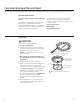
Care and cleaning of the vent hood. GEAppliances.com Be sure electrical power is off and all surfaces are cool before cleaning or servicing any part of the vent hood. Metal Grease Filter The metal filter traps grease released by foods from the cooktop. The filter also helps prevent flames (from food, grease) from damaging the inside of the hood. For this reason, the filter must ALWAYS be in place when the hood is in use.
Care and cleaning of the vent hood. Be sure electrical power is off and all surfaces are cool before cleaning or servicing any part of the vent hood. Stainless Steel Surfaces Do not use a steel wool pad; it will scratch the surface. To clean the stainless steel surface, use warm sudsy water or a stainless steel cleaner or polish. Always wipe the surface in the direction of the grain. Follow the cleaner instructions for cleaning the stainless steel surface.
Installation Instructions ? Chimney Vent Hoods Questions? Call 800.GE.CARES (800.432.2737) or Visit our Website at: GEAppliances.com BEFORE YOU BEGIN PRODUCT DIMENSIONS Read these instructions completely and carefully. IMPORTANT • ³ Save these instructions for local inspector’s use. • IMPORTANT ³ Observe all governing • • • • • • µ codes and ordinances. Note to Installer – Be sure to leave these instructions with the Consumer.
Installation Preparation PREPARE TO INSTALL THE HOOD INSTALLATION CLEARANCES ADVANCE PLANNING These vent hoods are designed to be installed onto a wall. They may be installed beneath a soffit or cabinet. ,QVWDOO WKHVH KRRGV µ 0LQ WR µ 0D[ DERYH WKH cooking surface. Ductwork Planning • This hood is designed to be vented vertically through the ceiling. A duct transition piece is VXSSOLHG IRU YHUWLFDO H[KDXVW 8VH ORFDOO\ VXSSOLHG elbows to vent horizontally through the rear wall. See page 10.
Installation Preparation POWER SUPPLY IMPORTANT – (Please read carefully) WARNING: FOR PERSONAL SAFETY, THIS APPLIANCE MUST BE PROPERLY GROUNDED. Remove house fuse or open circuit breaker before beginning installation. 'R QRW XVH DQ H[WHQVLRQ FRUG RU DGDSWHU SOXJ ZLWK this appliance. Follow National Electrical Codes or prevailing local codes and ordinances.
Installation Preparation DUCT FITTINGS This Hood Must Use an 8” Round Duct. It Can Transition WR D µ [ µ 'XFW Use this chart to compute PD[LPXP SHUPLVVLEOH OHQJWKV IRU duct runs to outdoors. Duct Piece Dimensions 8” Round, straight µ [ µ straight NOTE: 'R QRW H[FHHG PD[LPXP permissible equivalent lengths! 8” 90° elbow Maximum duct length: 100 feet. 8” 45° elbow Flexible ducting: ,I IOH[LEOH PHWDO GXFWLQJ LV XVHG all the equivalent feet values in the table should be doubled.
Installation Preparation TOOLS AND MATERIALS REQUIRED (NOT SUPPLIED) REMOVE THE PACKAGING CAUTION: Wear gloves to protect against sharp edges. Safety glasses Pencil and tape measure Spirit level Hammer Phillips screwdriver Flashlight • Remove the duct covers. • Remove the hardware bag, literature package and RWKHU ER[HG SDUWV • Remove and properly discard the protective plastic wrapping and other packaging materials. • Remove packing foam from behind the blower.
Installation Preparation CHECK INSTALLATION HARDWARE Locate the hardware package packed with the hood and check contents. HARDWARE PACKAGE Locate and count screws Stainless steel filter 4 wall fasteners 6 wood screws µ VFUHZ with wall µ anchor) long) WALL VENT IS 27-3/4" MIN.
Installation Preparation DETERMINE INSTALLATION HEIGHT • Telescopic duct covers are provided to conceal the ductwork running to the ceiling. • This hood can be installed for recirculating operation. Recirculating Kit included with hood. 28” 24” Min. µ 0D[ 36” Min. PV970, PV976 Upper Duct Cover 25.81 Lower Duct Cover 27.
Installation Instructions ,167$//$7,21³9(17(' 72 7+( 2876,'( DUCTWORK, WIRING LOCATIONS 'HWHUPLQH WKH H[DFW ORFDWLRQ RI WKH YHQW KRRG • Locate the template packed with the literature. –Measure 36” from the floor to the top of the cooking surface. Add hood installation height determined on pages 8 and 13. Mark that location. –Use a level to draw a straight pencil line on the wall. –Tape the template in position along the penciled line. CHECK TO BE SURE THE TEMPLATE IS LEVEL.
Installation Instructions 2 INSTALL HOOD MOUNTING SCREWS 3 INSTALL DUCT BRACKET The two upper mounting screws must enter the horizontal support or wall studs. • With the template taped in place, use a punch to mark mounting bracket screw locations. 'ULOO µ SLORW KROHV LQ RI WKH SXQFKHG ORFDWLRQV LQ WKH lower bracket. If the bottom 2 pilot holes do not enter ZRRG HQODUJH WKH KROHV WR µ DQG LQVWDOO PHWDO ZDOO fastener anchors (provided). • Remove the template.
Installation Instructions ,167$//$7,21³9(17(' 72 7+( 2876,'( 6 CONNECT ELECTRICAL 5 CONNECT DUCTWORK • Remove shipping tape from the damper. • Install ductwork, making connections in the direction of airflow as illustrated. 3XVK GXFW RYHU WKH H[KDXVW RXWOHW DQG GDPSHU • Secure joints in ductwork with sheet metal screws. • Wrap all duct joints and the flange connections with aluminized duct tape for an airtight seal. • 6HFXUH WKH KRXVH ZLULQJ WR WKH MXQFWLRQ ER[ with a strain relief (not provided).
Installation Instructions 7 INSTALL DUCT COVERS • Remove protective Mounting plastic covering. screws • Assemble duct covers according to application. NOTE: The inside duct cover has vent holes on one end. The holes are intended for use when the hood is installed for recirculating purposes. Slide the upper duct cover into the folded ends of the lower duct cover. • Place the decorative duct covers on top of the hood. 8 INSTALL METAL GREASE FILTER • Remove the protective film on the grease filter.
Installation Instructions ,167$//$7,21³5(&,5&8/$7,1* DUCTWORK, WIRING LOCATIONS 'HWHUPLQH WKH H[DFW ORFDWLRQ RI WKH YHQW KRRG • Locate the template packed with the literature. • Measure 36” from the floor to the top of the cooking surface. Add hood installation height determined on pages 8 and 13. Mark that location. 1 INSTALL FRAMING FOR HOOD SUPPORT IMPORTANT: Framing must be capable of supporting 100 lbs. • Tape the template in position along the penciled line.
Installation Instructions 2 INSTALL HOOD MOUNTING SCREWS The mounting screws must enter the horizontal support or wall studs. • With the template taped in place, use a punch to mark mounting bracket screw locations. 'ULOO µ SLORW KROHV LQ RI WKH SXQFKHG ORFDWLRQV LQ the lower bracket. If the bottom 2 pilot holes do not HQWHU ZRRG HQODUJH WKH KROHV WR µ DQG LQVWDOO PHWDO wall fastener anchors (provided). • Remove the template.
Installation Instructions ,167$//$7,21³5(&,5&8/$7,1* 4 MOUNT THE HOOD WARNING: 2 people are required to lift and position the hood onto the mounting screws. • Lift the hood onto the mounting screws. • If using a wall fastener, make sure the washer is in front of the flange and not behind it. Check with a level before tightening screws. • Install lower screws to pull the hood tight against the wall. 5 SIZE AND CUT DUCT PIECE • Measure from the bottom of the air deflector to the top of the hood as shown.
Installation Instructions 6 CONNECT ELECTRICAL Verify that power is turned off at the source. WARNING: If house wiring is not 2-wire with a ground wire, a ground must be provided by the installer. When house wiring is aluminum, be sure to XVH 8 / DSSURYHG DQWL R[LGDQW FRPSRXQG DQG aluminum-to-copper connectors. 5HPRYH WKH VFUHZV RQ WKH MXQFWLRQ ER[ FRYHU DQG the knockout on the top left side. Knockout Junction ER[ FRYHU 7 INSTALL DUCT COVERS Mounting screws • Remove protective plastic covering.
Installation Instructions ,167$//$7,21³5(&,5&8/$7,1* 8 INSTALL FILTERS Charcoal Filter Insert the charcoal filter into the opening. Push the latch on both sides toward the center and engage the flange. 9 FINALIZE INSTALLATION • Remove all tape and packaging materials. • Refer to the Operating Instructions in this manual to operate the hood. Metal Grease Filter • Remove the protective film on the grease filter. • Fit the tabs at the end of the filter into the slots in left side of the filter opening.
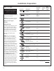
Before you call for service… Troubleshooting Tips Save time and money! Review the chart below first and you may not need to call for service. Problem Possible Causes What To Do Fan/Light does not operate when either button is pressed A house fuse may be blown or a circuit breaker tripped. • Replace fuse or reset circuit breaker. Fan does not operate when fan + or – buttons or MEMORY/OFF button is pressed The blower connector is loose or not plugged into its mating connector.
Before you call for service… Troubleshooting Tips Save time and money! Review the chart below first and you may not need to call for service. Problem Possible Causes What To Do Fan turned on by itself and is in MED setting. The fan setting can be adjusted but not to OFF. The heat sensor is activated. • This is normal when temperatures below the hood DUH H[FHHGLQJ WKH KHDW VHQVRU OLPLWV 5HPRYH WKH KHDW source under the hood or wait until the hood cools to appropriate levels.
GE Range Hood Warranty. All warranty service provided by our Factory Service Centers, or an authorized Customer Care® technician. To schedule service on-line, visit us at GEAppliances.com, or call 800. GE.CARES (800.432.2737). Please have serial number and model number available when calling for service. Staple your receipt here. Proof of the original purchase date is needed to obtain service under the warranty.
Consumer Support. GE Appliances Website GEAppliances.com Have a question or need assistance with your appliance? Try the GE Appliances Website 24 hours a day, any day of the year! For greater convenience and faster service, you can now download Owner’s Manuals, order parts or even schedule service on-line. Schedule Service GEAppliances.com ([SHUW *( UHSDLU VHUYLFH LV RQO\ RQH VWHS DZD\ IURP \RXU GRRU *HW RQ OLQH DQG VFKHGXOH \RXU VHUYLFH DW \RXU convenience any day of the year! Or call 800.GE.
Campanas de ventilación de chimenea GEAppliances.com Instrucciones de Seguridad . . . . . . . . . . . . . . 2, 3 Instrucciones de Operación Controles de la luz . . . . . . . . . . . . . . . 4 Controles de la ventilación . . . . . . . 4 Cuidado y limpieza Manual del Propietario e Instrucciones de Instalación PV970 PV976 Filtros de grasa . . . . . . . . . . . . . . . . . . 5 Luces de la campana . . . . . . . . . . . . 6 Superficies de acero inoxidable . .
INFORMACIÓN IMPORTANTE DE SEGURIDAD. LEA TODAS LAS INSTRUCCIONES ANTES DE SU USO. PRECAUCIONES DE SEGURIDAD ADVERTENCIA – PARA REDUCIR EL RIESGO DE INCENDIO, DESCARGA ELÉCTRICA O LESIONES A PERSONAS, CUMPLA CON LOS SIGUIENTES PUNTOS: A. Utilice esta unidad sólo de la manera concebida por el fabricante. Si tiene alguna pregunta, comuníquese con el fabricante. B.
GEAppliances.com PRECAUCIONES DE SEGURIDAD ADVERTENCIA – PARA REDUCIR EL RIESGO DE UN INCENDIO DE GRASA SOBRE UNA ESTUFA: A. Nunca deje unidades de superficie desatendidas en configuraciones de calor elevadas. Los alimentos que hierven y se derraman provocan humo y derrames grasosos que pueden prenderse fuego. Caliente los aceites lentamente en configuraciones bajas o medias. B. Siempre encienda (ON) la campana cuando cocine con configuraciones elevadas o cuando flambee alimentos (por ej.
Cómo usar los controles de la campana. MEMORY/OFF (memoria/apagado). Para configurar la memoria: A. Presione el botón MEMORY/OFF. B. Ingrese las configuraciones deseadas de ventilación y de luz. C. Presione el botón MEMORY/OFF de nuevo para guardar estas configuraciones.
Cuidado y limpieza de la campana de ventilación. GEAppliances.com Asegúrese de que la energía eléctrica esté apagada y que todas las superficies estén frías antes de limpiar o arreglar cualquier pieza de la campana de ventilación. Filtro de grasa metálico (O ILOWUR PHWiOLFR DWUDSD OD JUDVD liberada por los alimentos desde la estufa. El filtro también ayuda a evitar que las llamas (de los alimentos, grasa) dañen la parte interna de la campana.
Cuidado y limpieza de la campana de ventilación. Asegúrese de que la energía eléctrica esté apagada y que todas las superficies estén frías antes de limpiar o arreglar cualquier pieza de la campana de ventilación. Superficies de acero inoxidable No utilice almohadillas de acero porque rayan la superficie. Para limpiar la superficie de acero inoxidable, utilice agua tibia jabonosa o un limpiador o lustrador de acero inoxidable. Siempre limpie la superficie en dirección de la veta.
Instrucciones Campanas de ventilación de instalación de chimenea ¿Preguntas? Llame al 800.GE.CARES (800.432.2737) o visite nuestro sitio Web en: GEAppliances.com ANTES DE COMENZAR DIMENSIONES DEL PRODUCTO Lea estas instrucciones por completo y con detenimiento. • 10-7/8” IMPORTANTE ³ Guarde estas instrucciones para el uso de inspectores locales. • • • • • • • IMPORTANTE ³ Cumpla con todos los códigos y ordenanzas vigentes.
Preparación para la instalación PREPARACIÓN PARA INSTALAR LA CAMPANA ESPACIO DE INSTALACIÓN PLANIFICACIÓN PREVIA (VWDV FDPSDQDV GH YHQWLODFLyQ HVWiQ GLVHxDGDV para instalarse sobre una pared. Pueden instalarse debajo de un sofito o gabinete. • Instale estas campanas de 24” mínimo o 30” Pi[LPR VREUH OD VXSHUILFLH GH FRFFLyQ Planificación de conductos (VWD FDPSDQD HVWi GLVHxDGD SDUD YHQWLODUVH en forma vertical a través del cielorraso.
Preparación para la instalación SUMINISTRO DE ENERGÍA IMPORTANTE – (Tenga a bien leer cuidadosamente) ADVERTENCIA: PARA SEGURIDAD PERSONAL, ESTE APARATO DEBE CONECTARSE A TIERRA DE MANERA ADECUADA. Quite el fusible o abra el interruptor de circuitos antes de comenzar la instalación. No utilice un cable de extensión o un enchufe adaptador con este artefacto. Siga los Códigos Eléctricos Nacionales o códigos y ordenanzas locales vigentes.
Preparación para la instalación ACCESORIOS PARA CONDUCTOS Pieza de conducto Esta campana debe usar un conducto redondo de 8”. Puede conectarse a un conducto de 3-1/4” x 12”. Recto de 3-1/4” x 12” Utilice esta tabla para calcular ODV ORQJLWXGHV Pi[LPDV permitidas para recorridos de conductos hacia el exterior. Conductos flexibles: Si se utilizan conductos flexibles de metal, todos los valores equivalentes en pies de la tabla deben duplicarse.
Preparación para la instalación HERRAMIENTAS Y MATERIALES REQUERIDOS (NO SUMINISTRADOS) Gafas de seguridad /iSL] \ FLQWD PpWULFD Nivel de burbuja de aire Destornillador de estrella Martillo QUITE EL ENVOLTORIO PRECAUCIÓN: Se guantes para protegerse de los bordes afilados. • Quite las cubiertas de los conductos. • Quite la bolsa de piezas, el paquete de instrucciones y otras piezas en cajas. • Quite y descarte adecuadamente el envoltorio SOiVWLFR GH SURWHFFLyQ \ RWURV PDWHULDOHV de empaque.
Preparación para la instalación CONTROLE LAS PIEZAS DE INSTALACIÓN Ubique el paquete de hardware embalado con la campana y verifique los contenidos.
Preparación para la instalación DETERMINE LA ALTURA DE INSTALACIÓN • Se ofrecen cubiertas plegables para ocultar los conductos que se extienden hasta el cielorraso. • Esta campana puede instalarse para una operación de recirculación. Se incluye un kit de recirculación con la campana. 24” Mín. µ 0i[ PV970, PV976 Cubierta de conducto superior 25.81 Cubierta de conducto inferior 27.
Instrucciones de instalación ,167$/$&,Ï1³9(17,/$&,Ï1 +$&,$ (/ (;7(5,25 UBICACIONES DE LOS CONDUCTOS Y CABLEADO Determine la ubicación exacta de la campana de ventilación. • Ubique la plantilla embalada con las instrucciones. –Mida 36” desde el piso hasta el extremo superior de la superficie de cocción. Agregue la altura de instalación de la campana determinada HQ ODV SiJLQDV \ 0DUTXH HVD XELFDFLyQ –Utilice un nivel para dibujar una línea recta en lápiz sobre la pared.
Instrucciones de instalación 2 INSTALE LOS TORNILLOS DE MONTAJE DE LA CAMPANA 3 INSTALE EL SOPORTE DEL CONDUCTO Los dos tornillos de montaje superiores deben ingresar en el soporte horizontal o en las columnas de pared. • Con la plantilla adherida con cinta en su lugar, utilice una perforadora para marcar las ubicaciones de los tornillos del soporte de montaje. • Perfore orificios piloto de 1/8” en 4 de las ubicaciones perforadas en el soporte inferior.
Instrucciones de instalación ,167$/$&,Ï1³9(17,/$&,Ï1 +$&,$ (/ (;7(5,25 5 CONECTE LOS CONDUCTOS • Quite la cinta de embalaje del regulador de tiro. • Instale el conducto, realizando conexiones en la dirección del flujo de aire, como se ilustra. • Presione el conducto sobre la salida de escape y el regulador de tiro. • Ajuste las juntas del conducto con tornillos para placas de metal.
Instrucciones de instalación 7 INSTALE LAS CUBIERTAS DEL CONDUCTO Tornillos • Quite la tapa protectora de montaje GH SOiVWLFR • Arme las cubiertas del conducto de acuerdo con la aplicación. NOTA: La cubierta del conducto interior cuenta con orificios de ventilación en un extremo. /RV RULILFLRV HVWiQ SURYLVWRV SDUD VHU XWLOL]DGRV cuando la campana se instala para efectuar una recirculación. Deslice la cubierta del conducto superior dentro de los extremos doblados de la cubierta del conducto inferior.
Instrucciones de instalación ,167$/$&,Ï1³5(&,5&8/$&,Ï1 UBICACIONES DE LOS CONDUCTOS Y CABLEADO 1 INSTALE EL ARMAZÓN PARA EL SOPORTE DE LA CAMPANA • Determine la ubicación exacta de la campana de ventilación. IMPORTANTE: El armazón debe poder • Ubique la plantilla empacada con las instrucciones. soportar 100 lbs. • Mida 36” desde el piso hasta el extremo superior de la superficie de cocción.
Instrucciones de instalación 2 INSTALE LOS TORNILLOS DE MONTAJE DE LA CAMPANA 3 INSTALE EL SOPORTE DEL CONDUCTO Y EL DEFLECTOR Los tornillos de montaje deben ingresar en el soporte horizontal o en las columnas de pared. • Con la plantilla adherida con cinta en su lugar, utilice una perforadora para marcar las ubicaciones de los tornillos del soporte de montaje. • Perfore orificios piloto de 1/8” en 4 de las ubicaciones perforadas en el soporte inferior.
Instrucciones de instalación ,167$/$&,Ï1³5(&,5&8/$&,Ï1 4 INSTALE LA CAMPANA ADVERTENCIA: Se necesitan 2 personas para levantar y colocar la campana sobre los tornillos de montaje. • Levante la campana y colóquela sobre los tornillos de montaje. • Si utiliza una sujeción de pared, verifique que las DUDQGHODV HVWpQ DGHODQWH GH OD EULGD \ QR GHWUiV Controle con un nivel antes de ajustar los tornillos. • Instale los tornillos inferiores para ajustar la campana bien contra la pared.
Instrucciones de instalación 6 CONECTE LOS ELEMENTOS ELÉCTRICOS Verifique que la energía esté cortada en la fuente. ADVERTENCIA: Si el cableado doméstico no cuenta con un cable de 2 hilos con conexión a tierra, un instalador debe realizar una conexión a tierra. Cuando el cableado doméstico es de aluminio, asegúrese de usar un compuesto antioxidante y conectores de aluminio a cobre aprobados por UL. • Quite los 6 tornillos de la tapa de la caja de conexiones y el calado sobre la parte superior izquierda.
Instrucciones de instalación ,167$/$&,Ï1³5(&,5&8/$&,Ï1 8 INSTALE LOS FILTROS Filtro de carbón Introduzca el filtro de carbón dentro de la abertura. Presione la traba sobre ambos lados hacia el centro y sujete la brida. 9 FINALICE LA INSTALACIÓN • Quite toda la cinta y material de empaque. • Consulte las Instrucciones de operación de este manual para operar la campana. Filtro de grasa metálico • Quite la película protectora del filtro de grasa.
Antes de llamar al servicio técnico… Consejos para identificación y solución de problemas ¡Ahorre tiempo y dinero! Lea la siguiente tabla primero y quizás no necesite llamar al servicio técnico. Problema Causas posibles Qué hacer El ventilador/la luz no funcionan cuando se presionan los botones El fusible puede haberse quemado o el interruptor de circuitos puede haber saltado. • Cambie los fusibles o reconfigure el interruptor de circuitos.
Antes de llamar al servicio técnico… Consejos para identificación y solución de problemas ¡Ahorre tiempo y dinero! Lea la siguiente tabla primero y quizás no necesite llamar al servicio técnico. Problema Causas posibles Qué hacer El ventilador se encendió solo y se encuentra en la configuración MED (media). La configuración de ventilador puede puede ajustarse pero no apagarse (OFF). Se encuentra activado el sensor • Esto es normal cuando las temperaturas debajo de de calor.
Garantía de GE campanas de ventilación. Todos los servicios de garantía los proporcionan nuestros Centros de Reparación de Fábrica o nuestros técnicos Customer Care® autorizados. Para concertar una cita de reparación, en línea, visítenos en GEAppliances.com, o llame al 800.GE.CARES (800.432.2737). Cuando llame para solicitar servicio, por favor tenga a mano el número de serie y el número de modelo. Peque aquí su recibo.
Apoyo al consumidor. Página Web de GE Appliances GEAppliances.com ¢7LHQH DOJXQD SUHJXQWD VREUH VX HOHFWURGRPpVWLFR" £3UXHEH OD SiJLQD :HE GH *( $SSOLDQFHV FXDOTXLHU GtD GHO DxR 3DUD PD\RU FRQYHQLHQFLD \ VHUYLFLR PiV UiSLGR \D SXHGH GHVFDUJDU ORV 0DQXDOHV GH ORV 3URSLHWDULRV pedir piezas o incluso hacer una cita en línea para que vengan a realizar una reparación. Solicite una reparación GEAppliances.