Vented Range Hoods GEAppliances.com Owner’s Manual and Installation Instructions Safety Instructions . . . . . . . . . . . 2 Operating Instructions Fan Control . . . . . . . . . . . . . . . . . . . . . . 3 Light Control . . . . . . . . . . . . . . . . . . . . . 4 JV936 JV966 CV936 CV966 Care and Cleaning Grease Filters . . . . . . . . . . . . . . . . . . . . 5 Hood Lights . . . . . . . . . . . . . . . . . . . . . . 6 Stainless Steel Surfaces . . . . . . . . . . 5 Installation Instructions. .
IMPORTANT SAFETY INFORMATION. READ ALL INSTRUCTIONS BEFORE USING. SAFETY PRECAUTIONS WARNING – TO REDUCE THE RISK OF FIRE, ELECTRIC SHOCK OR INJURY TO PERSONS, OBSERVE THE FOLLOWING: A. Use this unit only in the manner intended by the manufacturer. If you have questions, contact the manufacturer. B. Before servicing or cleaning unit, switch power off at service panel and lock the service disconnecting means to prevent power from being switched on accidentally.
Using the hood controls. GEAppliances.com Throughout this manual, features and appearance may vary from your model. FAN Control LIGHT Control Turn the FAN speed control to LO, MED LO, MED HI or HI, as needed. Turn the LIGHT control to HI for bright light while cooking. Turn to NITE for use as a night light. Continuous use of the fan system while cooking helps keep the kitchen comfortable and less humid. It also reduces cooking odors and soiling moisture that create a frequent need for cleaning.
Care and cleaning of the vent hood. Be sure electrical power is off and all surfaces are cool before cleaning or servicing any part of the vent hood. Reusable Metal Grease Filters The hood has 2 metal reusable grease filters. The metal filters trap grease released by foods on the cooktop. They also help prevent flaming foods on the cooktop from damaging the inside of the hood. For this reason, the filters must ALWAYS be in place when the hood is used.
GEAppliances.com Be sure electrical power is off and all surfaces are cool before cleaning or servicing any part of the vent hood. Receptacle Socket Hood Lights NOTE: The glass cover should be removed only when cold. Wearing latex gloves may offer a better grip. Receptacle CAUTION: Bulb Glass cover Before replacing your light bulb, disconnect the electrical power to the hood at the main fuse or circuit breaker panel. Be sure to let the light cover and bulb cool completely.
Installation Instructions Range Hoods Questions? Call 800.GE.CARES (800.432.2737) or visit our Website at: www.GEAppliances.com. BEFORE YOU BEGIN PRODUCT DIMENSIONS Read these Instrucitons completely and carfully. • IMPORTANT ³ Save these instructions 12” for local inspector’s use. • IMPORTANT ³ Observe all governing codes and ordinances. • Note to Installer ³ Be sure to leave these • Note to Consumer ³ Keep these instrucitons 18” instructions with the Consumer. for future reference.
Installation Instructions INSTALLATION CLEARANCES OPTIONAL ACCESSORIES These vent hoods are designed to be installed onto a wall. They may be installed beneath a soffit or cabinet. • Install these hoods 24” Min. to 36” Max. above the cooking space. Duct Cover A decorative duct cover is available to accommodate 8 to 10 ft. ceiling heights. The duct cover will expand from 12” Min. or 24” to 36” Max. height. • The duct cover conceals the ductwork running from the top of the hood to the ceiling.
Installation Instructions ADVANCE PLANNING DECORATIVE DUCT COVERS Ductwork Planning • This hood may be vented vertically through upper cabinets, soffit or ceiling. A duct transition piece is supplied for vertical exhaust. Use locally supplied elbows to vent horizontally through the rear wall. See page 13. • Determine the exact location of the vent hood. • Plan the route for venting exhaust to the outdoors. • Use the shortest and straightest duct route possible.
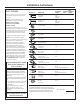
Installation Instructions DUCT FITTINGS Use this chart to compute maximum permissible lengths for duct runs to outdoors. Note: Do not exceed maximum permissible equivalent lengths! Maximum duct length: 100 foot for vent hoods. Flexible ducting: If flexible metal ducting is used, all the equivalent feet values in the table should be doubled. The flexible metal duct should be straight and smoot and extended as much as possible. Do NOT use flexible plastic ducting.
Installation Instructions TOOLS AND MATERIALS REQUIRED REMOVE THE PACKAGING (NOT SUPPLIED) Pencil and tape measure • Remove the small box housing the motor. • Lift the hood out of the box. Phillips and Flat blade screwdirvers Duct tape Hood 1/4” pivoting hex socket Wood Mounting Support Electric drill with 1/8” and 3/8” bits Motor Parts Package Shipping Carton Safety glasses • Remove shipping screws holding the wood mounting piece to the back side of the hood.
Installation Instructions PARTS PROVIDED Locate the hardware accessory box packed with the hood and check contents. 2 Aluminum Grease Filters Screws, wall fasteners, washers Duct Transition with Damper DUCT COVER REQUIREMENTS Review the following examples to ensure a trouble free installation using the duct cover 8 ft. Ceiling accessory. We recommend that the vent hood and decorative duct cover (if used) be on site before final framing and wall finishing.
Installation Instructions DETERMINE HOOD, DUCTWORK AND WIRING LOCATIONS • Keep the wood support piece and its screws for later installaton. Do not discard. • Measure desired distance from the bottom of the hood to the cooking surface, 24” min. to 36” max. Refer to the previous page if the accessory duct cover will be used. • Use a level to draw a horizontal line indicating the bottom of the hood. • Use a level to draw the cooktop centerline location.
Installation Instructions 1 INSTALL HOOD SUPPORT 2 INSTALL TRANSITION IMPORTANT: Remove shipping tape from damper and check that damper moves freely. IMPORTANT : Framing must be capable of supporting 100 lbs. • Locate at least 2 vertical studs at the wood mounting location by tapping drywall with a hammer or use a stud finder. • Center the supplied wood horizontal support, left to right, and below the marked line.
Installation Instructions 4 Alternate Mounting Method IMPORTANT : For additional support and to minimize vibration during operation, we strongly recommend that the hood also be secured to the back wall with wall fastners. INSTALL HOOD TO SOFFIT OR BENEATH CABINETS 30” Models SKIP THIS STEP IF USING WALL MOUNTING METHOD 2-9/16” IMPORTANT : Soffit framing must be capable of supporting 100 lbs.
Installation Instructions 5 INSTALL CEILING BRACKET 6 CONNECT DUCTWORK The ceiling bracket must be installed when the duct cover is used to span 24” or more height above the hood. The bracket will hold the decorative duct cover in place at the top. Note: The ceilling bracket is not required when using only the 12” section of the duct cover. • Install the 2 small screws into the sides of the duct bracket. remove the screws. Pre-tapping the holes will insue ease of final installation.
Installation Instructions 9 INSTALL DUCT COVERS 7 INSTALL MOTOR • Align and engage the slots in the blower assemly to the 3 hooks at the rear of the exhaust opening. • Rotate motor uplards until it aligns with the attachment screw location. • Secure the motor to attachment bracket at the front of the opening with washer and screw provided. • Plug the motor connector into the mating hood connector. Seethe illustration for the hood connector location. Touch the hood to locate and make the connection.
Installation Instructions 11 INSTALL FILTERS 12 FINALIZE INSTALLATION • Remove protective film covering the filters. • Insert the filter into the “C” clips mounted to the top of the vertical front panel. • Tap the filter against one side to align with outside opening. • Pull the filter down into the lower slots at the bottom of the filter support. • Refer to the operating instructions to test all controls.
Before you call for service… Troubleshooting Tips Save time and money! Review the chart below first and you may not need to call for service. Problem Possible Causes What To Do Fan does not operate when the switch is on A fuse may be blown or a circuit breaker tripped. • Replace fuse or reset circuit breaker. The blower connector is loose or not plugged into its mating connector. • Disconnect power to the unit. Remove the filters and look up at the blower.
Please place in envelope and mail to: Veuillez mettre dans une enveloppe et envoyez à : OWNERSHIP REGISTRATION P.O.
GE Range Hood Warranty. All warranty service provided by our Factory Service Centers, or an authorized Customer Care® technician. To schedule service on-line, visit us at GEAppliances.com, or call 800. GE.CARES (800.432.2737). Please have serial number and model number available when calling for service. Staple your receipt here. Proof of the original purchase date is needed to obtain service under the warranty.
Consumer Support. GE Appliances Website GEAppliances.com Have a question or need assistance with your appliance? Try the GE Appliances Website 24 hours a day, any day of the year! For greater convenience and faster service, you can now download Owner’s Manuals, order parts or even schedule service on-line. Schedule Service GEAppliances.com Expert GE repair service is only one step away from your door. Get on-line and schedule your service at your convenience any day of the year! Or call 800.GE.
Hotte de cuisine à évacuation www.electromenagersge.ca Consignes de sécurité . . . . . . . . 2 Manuel d’utilisation et directives d’installation Directives de fonctionnement Commande de la lampe . . . . . . . . . . 3 Commande du ventilateur . . . . . . . . 3 JV936 JV966 CV936 CV966 Entretien et nettoyage Filtres à graisses . . . . . . . . . . . . . . . . . 4 Lampe de la hotte . . . . . . . . . . . . . . . . 5 Surfaces en acier inoxydable . . . . . 4 Directives d’installation . . .6–17 Dépannage . .
CONSIGNES DE SÉCURITÉ IMPORTANTES. VEUILLEZ LIRE TOUTES LES CONSIGNES AVANT D’UTILISER L’APPAREIL. CONSIGNES DE SÉCURITÉ AVERTISSEMENT – AFIN DE RÉDUIRE LES RISQUES D’INCENDIE, DE CHOC ÉLECTRIQUE OU DE BLESSURES, VEUILLEZ OBSERVER LES CONSIGNES QUI SUIVENT : A. N’utilisez cet appareil que pour l’usage pour lequel il a été conçu par le fabricant. Pour toute question, communiquez avec le fabricant. B.
Utilisation des commandes de la hotte. www.electromenagersge.ca Dans le présent manuel, les caractéristiques et l’apparence peuvent être différentes de celles de votre modèle. Commande du VENTILATEUR Commande de la LAMPE Tournez la commande de vitesse FAN (Ventilateur) à LO (Minimum), MED LO (Minimum/moyen), MED HI (Moyen/maximum) ou HI (Maximum), selon le besoin. Tournez la commande LIGHT (Lampe) à HI (Maximum) pour éclairer la surface de cuisson.
Entretien et nettoyage de la hotte. Assurez-vous que l’alimentation électrique est coupée et que toutes les surfaces sont froides avant de nettoyer ou de réparer toute partie de la hotte. Filtres à graisses métalliques réutilisables La hotte est dotée de deux filtres à graisses métalliques réutilisables. Les filtres métalliques retiennent la graisse qui s’échappe des aliments qui cuisent sur la surface de cuisson.
www.electromenagersge.ca Assurez-vous que l’alimentation électrique est coupée et que toutes les surfaces sont froides avant de nettoyer ou de réparer toute partie de la hotte. Prise Douille Lampe de la hotte REMARQUE : Enlevez le capot en verre lorsqu’il est froid seulement. Vous pouvez porter des gants en latex pour le saisir plus facilement.
Directives d’installation Hottes de cuisine Des questions? Appelez au 1.800.561.3344 ou visitez notre site Web à l’adresse www.electromenagersge.ca AVANT DE COMMENCER DIMENSIONS DU PRODUIT Veuillez lire attentivement toutes les directives qui suivent. 30,4 cm (12 po) IMPORTANT • ³ Conservez les présentes directives pour l’inspecteur local. • ³ Observez tous les codes et règlements en vigueur.
Directives d’installation DÉGAGEMENTS POUR L’INSTALLATION ACCESSOIRES FACULTATIFS Cette hotte à évacuation a été conçue pour être installée sur un mur. Elle peut être installée sous une retombée de plafond ou une armoire. • Installez la hotte à une hauteur variant entre 60,9 cm (24 po) et 91,4 cm (36 po) au-dessus de la surface de cuisson. Couvre-conduit Il existe un couvre-conduit décoratif pour les installations lorsque la hauteur du plafond varie entre 2,4 m (8 pi) et 3,0 m (10 pi).
Directives d’installation PRÉPARATIFS COUVRE-CONDUIT DÉCORATIF Préparatifs concernant le conduit d’évacuation • Cette hotte peut être dotée d’un conduit d’évacuation vertical à travers les armoires supérieures, la retombée de plafond ou le plafond. Un conduit de transition est fourni pour l’évacuation à la verticale. Utilisez des coudes disponibles en quincaillerie pour évacuer l’air horizontalement à travers le mur arrière. Reportez-vous à la page 13. • Déterminez l’emplacement exact de la hotte.
Directives d’installation RACCORDS DE CONDUIT Utilisez ce tableau pour calculer la longueur maximale permise du conduit d’évacuation vers l’extérieur. Remarque : Ne dépassez pas la longueur équivalente maximale permise! Longueur maximale du conduit : 30,4 m (100 pi) pour une hotte. Conduit flexible : Si vous utilisez un conduit flexible en métal, il faut doubler toutes les longueurs équivalentes indiquées dans le tableau. Le conduit métallique flexible doit être droit et souple, et étiré le plus possible.
Directives d’installation MATÉRIEL ET OUTILS NÉCESSAIRES DÉBALLAGE (NON FOURNIS) Crayon et ruban à mesurer • Enlevez la petite boîte qui protège le moteur. • Sortez la hotte de la boîte.
Directives d’installation PIÈCES FOURNIES Repérez la boîte contenant les accessoires fournis avec la hotte, et vérifiez-en le contenu. 2 filtres à graisses en aluminium Vis, chevilles d’ancrage, rondelles Conduit de transition avec registre EXIGENCES CONCERNANT LE COUVRE-CONDUIT Support de filtre Passez en revue les exemples qui suivent afin d’installer sans problème le couvre-conduit décoratif.
Directives d’installation EMPLACEMENT DE LA HOTTE, DU CONDUIT ET DU CÂBLAGE Conduit à travers une retombée de plafond ou une armoire supérieure : • Suivez la procédure indiquée pour l’installation du conduit dans le plafond pour pratiquer un orifice de 19,0 cm (7 1/2 po) de diamètre à travers la retombée de plafond ou l’armoire. • Reportez-vous à l’étape 4 de la page 15 pour pratiquer l’ouverture pour le conduit de transition.
Directives d’installation 1 INSTALLATION DU SUPPORT DE 2 INSTALLATION DU CONDUIT LA HOTTE DE TRANSITION IMPORTANT : Retirez le ruban gommé qui retient le registre en place et vérifiez si le registre bouge librement. IMPORTANT : La charpente doit être en mesure de soutenir une charge de 45,3 kg (100 lb). • Repérez au moins deux montants verticaux pour fixer le support en bois en frappant sur la cloison sèche avec un marteau ou en utilisant un localisateur de montants.
Directives d’installation 4 Autre méthode de montage IMPORTANT : Pour un soutien supplémentaire et pour réduire au minimum les vibrations pendant le fonctionnement de l’appareil, nous vous recommandons fortement de fixer également la hotte au mur à l’aide de chevilles d’ancrage pour mur creux.
Directives d’installation 5 INSTALLATION DU SUPPORT 6 RACCORDEMENT DU CONDUIT DE PLAFOND • Insérez le conduit sur l’extrémité du conduit de transition jusqu’à ce qu’il atteigne les languettes d’arrêt. • Installez le conduit en effectuant le raccord dans le sens du débit d’air, comme indiqué dans l’illustration. • Fixez les raccords du conduit à l’aide de vis à tôle. • Appliquez du ruban adhésif pour conduit pour sceller tous les raccords.
Directives d’installation 9 INSTALLATION DU COUVRE-CONDUIT 7 INSTALLATION DU MOTEUR • Placez les fentes du ventilateur visà-vis des trois crochets à l’arrière de l’orifice d’évacuation, puis insérez les crochets dans les fentes. • Tournez le moteur vers le haut jusqu’à ce qu’il soit vis-à-vis de l’emplacement de la vis de fixation. • Fixez le moteur au support de fixation à l’avant de l’ouverture à l’aide de la vis et de la rondelle fournies.
Directives d’installation 11 INSTALLATION DES FILTRES 12 FIN DE L’INSTALLATION • Enlevez la pellicule protectrice qui recouvre les filtres. • Insérez le filtre dans les agrafes installées à la partie supérieure du panneau avant vertical. • Donnez des petits coups sur le côté du filtre afin qu’il soit vis-à-vis de l’ouverture extérieure. • Poussez sur le filtre afin qu’il soit inséré dans les fentes inférieures, au bas du support de filtre.
Avant d’appeler un réparateur… Conseils de dépannage Gagnez du temps et économisez de l’argent! Consultez d’abord le tableau au-dessous. Vous pourriez vous éviter d’appeler un réparateur. Problème Causes possibles Correctifs Le ventilateur ne fonctionne pas lorsque la commande est actionnée Un fusible peut être grillé ou un disjoncteur déclenché. • Remplacez le fusible ou réenclenchez le disjoncteur. Le connecteur du ventilateur est lâche ou débranché. • Coupez l’alimentation électrique de la hotte.
Notes.
Notes.
Garantie GE de la hotte de cuisine. Toutes les réparations sous garantie sont effectuées par nos Centres de réparation ou par nos réparateurs Mabe autorisés. Pour obtenir du service en ligne, veuillez nous visiter au site www. electromenagersge.ca ou appelez le no 1.800.561.3344. Veuillez fournir le numéro de série et le numéro de modèle lorsque vous appelez pour obtenir le service. Agrafez votre facture ici. La preuve d’achat originale sera nécessaire pour bénéficier des services de garantie.
Service à la clientèle. Site Web appareils électroménagers GE www.electromenagersge.ca Vous avez une question ou vous avez besoin d’aide pour votre appareil électroménager? Contactez-nous par Internet au site www.electromenagersge.ca 24 heures par jour, tous les jours de l’année. Service de réparations 1.800.561.3344 Service de réparations GE est tout près de vous. Pour faire réparer votre électroménager GE, il suffit de nous téléphoner.