Vented Range Hoods ge.com Safety Instructions . . . . . . . . 2, 3 Operating Instructions Light Controls . . . . . . . . . . . . . . .4 Vent Controls . . . . . . . . . . . . . . .4 Care and Cleaning Grease Filters . . . . . . . . . . . . . . . .5 Hood Lights . . . . . . . . . . . . . . . .6 Hood Surfaces . . . . . . . . . . . . . . .5 Stainless Steel Surfaces . . . . . . . .5 Owner’s Manual and Installation Instructions JV935 JV936 JV965 JV966 Installation Instructions . . .7–18 Troubleshooting Tips .
SAFETY PRECAUTIONS WARNING – TO REDUCE THE RISK OF FIRE, WARNING – TO REDUCE THE RISK OF ELECTRIC SHOCK OR INJURY TO PERSONS, OBSERVE THE FOLLOWING: A. Use this unit only in the manner intended by the manufacturer. If you have questions, contact the manufacturer. B. Before servicing or cleaning unit, switch power off at service panel and lock the service disconnecting means to prevent power from being switched on accidentally.
SAFETY PRECAUTIONS WARNING – TO REDUCE THE RISK OF WARNING – TO REDUCE THE RISK OF FIRE, USE ONLY METAL DUCTWORK. ■ Do not attempt to repair or replace any part of your hood unless it is specifically recommended in this manual. All other servicing should be referred to a qualified technician. Operating Instructions A RANGE TOP GREASE FIRE: A. Never leave surface units unattended at high settings. Boilovers cause smoking and greasy spillovers that may ignite. Heat oils slowly on low or medium settings.
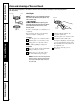
Throughout this manual, features and appearance may vary from your model. Operating Instructions Safety Instructions Using the hood controls. FAN Control LIGHT Control Turn the FAN speed control to LO, MED LO, MED HI or HI, as needed. Turn the LIGHT control to HI for bright light while cooking. Turn to NITE for use as a night light. Care and Cleaning Continuous use of the fan system while cooking helps keep the kitchen comfortable and less humid.
ge.com Be sure electrical power is off and all surfaces are cool before cleaning or servicing any part of the vent hood. Reusable Metal Grease Filters The hood has 2 metal reusable grease filters. If it ever becomes necessary to replace the metal grease filters, they may be ordered from your GE supplier. Heavy-duty commercial filters may also be used in place of the filters. For 36″ hoods, order Kit no. JXBF36SS. To order, call 800.626.2002.
Be sure electrical power is off and all surfaces are cool before cleaning or servicing any part of the vent hood. Receptacle Socket Hood Lights NOTE: The glass cover should be removed only when cold. Wearing latex gloves may offer a better grip. Receptacle CAUTION: Before replacing your Operating Instructions Safety Instructions Care and cleaning of the vent hood. Bulb Glass cover light bulb, disconnect the electrical power to the hood at the main fuse or circuit breaker panel.
Installation Instructions Range Hoods Questions? Call 800.GE.CARES (800.432.2737) or Visit our Website at: ge.com www.GEAppliances.com BEFORE YOU BEGIN PRODUCT DIMENSIONS Read these instructions completely and carefully. • 12" IMPORTANT – Save these instructions for local inspector’s use. IMPORTANT – Observe all governing codes and ordinances. • Note to Installer – Be sure to leave these instructions with the Consumer. • Note to Consumer – Keep these instructions for future reference.
Installation Instructions INSTALLATION CLEARANCES OPTIONAL ACCESSORIES These vent hoods are designed to be installed onto a wall. They may be installed beneath a soffit or cabinet. • Install these hoods 24 ″ Min. to 36 ″ Max. above the cooking surface. Duct Cover A Decorative duct cover is available to accommodate 8 to 10 ft. ceiling heights. The duct cover will expand from 12″ Min. or 24 ″ to 34 ″ Max. height. • The duct cover conceals the ductwork running from the top of the hood to the ceiling.
Installation Instructions ADVANCE PLANNING DECORATIVE DUCT COVERS Ductwork Planning • This hood may be vented vertically through upper cabinets, soffit or ceiling. A duct transition piece is supplied for vertical exhaust. Use locally supplied elbows to vent horizontally through the rear wall. See page 13. • Determine the exact location of the vent hood. • Plan the route for venting exhaust to the outdoors. • Use the shortest and straightest duct route possible.
Installation Instructions DUCT FITTINGS Duct Piece Dimensions Use this chart to compute maximum permissible lengths for duct runs to outdoors. Note: Do not exceed maximum permissible equivalent lengths! Maximum duct length: 100 foot for vent hoods. Flexible ducting: If flexible metal ducting is used, all the equivalent feet values in the table should be doubled. The flexible metal duct should be straight and smooth and extended as much as possible. Do NOT use flexible plastic ducting.
Installation Instructions TOOLS AND MATERIALS REQUIRED (NOT SUPPLIED) REMOVE THE PACKAGING • Lift out the wooden crossmember, as well as the top protective carton. • Lift out the four “L” shaped polystyrene protection profiles. Pencil and tape measure • Remove the protection moldings around the smaller carton box. • Remove the small box housing the motor. • Lift the hood out of the box.
Installation Instructions PARTS PROVIDED Locate the hardware accessory box packed with the hood and check contents. Screws, wall fasteners, washers Filter Support 2 Aluminum Grease Filters 2 Control Knobs DUCT COVER REQUIREMENTS Review the following examples to ensure a trouble free installation using the duct cover accessory. We recommend that the vent hood and decorative duct cover (if used) be on site before final framing and wall finishing.
Installation Instructions DETERMINE HOOD, DUCTWORK AND WIRING LOCATIONS • Measure desired distance from the bottom of the hood to the cooking surface, 24″ min. to 36″ Max. Refer to the previous page if the accessory duct cover will be used. • Use a level to draw a horizontal line indicating the bottom of the hood. • Use a level to draw the cooktop centerline location. • Measure 15-3/8 ″ up from the horizontal line for the bottom of the hood. Draw another horizontal line.
Installation Instructions 1 INSTALL HOOD SUPPORT 2 INSTALL TRANSITION IMPORTANT: Framing must be capable of supporting 100 lbs. IMPORTANT: Remove shipping tape from damper and check that damper moves freely. • Locate at least 2 vertical studs at the wood mounting location by tapping drywall with a hammer or use a stud finder. • Center the supplied wood horizontal support, left to right and below the marked line. Duct Transition 7" Min.
Installation Instructions 4 Alternate Mounting Method INSTALL HOOD TO SOFFIT OR BENEATH CABINETS IMPORTANT: For additional support and to minimize vibration during operation, we strongly recommend that the hood also be secured to the back wall with wall fasteners. 30" Models SKIP THIS STEP IF USING WALL MOUNTING METHOD 2-9/16" 2-3/8" IMPORTANT: Soffit framing must be capable of supporting 100 lbs.
Installation Instructions 5 INSTALL CEILING BRACKET 6 CONNECT DUCTWORK The ceiling bracket must be installed when the duct cover is used to span 24″ or more height above the hood. The bracket will hold the decorative duct cover in place at the top. Note: The ceiling bracket is not required when using only the 12 ″ section of the duct cover. • Install the 2 small screws into the sides of the duct bracket. Remove the screws. Pre-tapping the holes will insure ease of final installation.
Installation Instructions 7 INSTALL MOTOR • Align and engage the slots in the blower assembly to the 3 hooks at the rear of the exhaust opening. 9 INSTALL DUCT COVERS To install the 12 ″ duct cover alone: • Place the 12″ section of the decorative duct cover on top of the hood. • Secure the cover to the top of the hood with 4 screws provided. To install the 2-piece duct cover: • Place the 2-piece duct cover on top of the hood. • Secure the bottom cover to the top of the hood with 4 screws provided.
Installation Instructions 11 INSTALL FILTERS 11A INSTALL OPTIONAL COMMERCIAL FILTERS • Remove protective film covering the filters. • Insert the filter into the “C” clips mounted to the top of the vertical front panel. • Tap the filter against one side to align with outside opening. • Pull the filter down into the lower slots at the bottom of the filter support. • Remove supplied filters (if installed).
Operating Instructions Care and Cleaning Troubleshooting Tips Consumer Support 19 Safety Instructions ge.com Notes.
Safety Instructions Troubleshooting Tips Save time and money! Review the charts on the following pages first and you may not need to call for service. Problem Possible Causes What To Do Fan does not operate when the switch is on A fuse may be blown or a circuit breaker tripped. • Replace fuse or reset circuit breaker. The blower connector is loose or not plugged into its mating connector. •Disconnect power to the unit. Remove the filters and look up at the blower.
GE Service Protection Plus™ GE, a name recognized worldwide for quality and dependability, offers you Service Protection Plus ™—comprehensive protection on all your appliances— No Matter What Brand! Benefits Include: • Backed by GE • All brands covered • Unlimited service calls • All parts and labor costs included • No out-of-pocket expenses • No hidden deductibles • One 800 number to call We’ll Cover Any Appliance. Anywhere. Anytime.
Consumer Product Ownership Registration Dear Customer: Thank you for purchasing our product and thank you for placing your confidence in us. We are proud to have you as a customer! Follow these three steps to protect your new appliance investment: 1 2 3 Complete and mail your Consumer Product Ownership Registration today. Have the peace of mind of knowing we can contact you in the unlikely event of a safety modification. After mailing the registration below, store this document in a safe place.
All warranty service provided by our Factory Service Centers, or an authorized Customer Care® technician. To schedule service, on-line, 24 hours a day, visit us at ge.com, or call 800.GE.CARES (800.432.2737). Please have serial number and model number available when calling for service. Staple your receipt here. Proof of the original purchase date is needed to obtain service under the warranty.
Consumer Support. GE Appliances Website ge.com Have a question or need assistance with your appliance? Try the GE Appliances Website 24 hours a day, any day of the year! For greater convenience and faster service, you can now download Owner’s Manuals, order parts or even schedule service on-line. Schedule Service ge.com Expert GE repair service is only one step away from your door. Get on-line and schedule your service at your convenience 24 hours any day of the year! Or call 800.GE.CARES (800.432.