Radiant Downdraft Cooktop GEAppliances.com For a Spanish version of this manual, visit our Website at GEAppliances.com. Para consultar una version en español de este manual de instrucciones, visite nuestro sitio de internet GEAppliances.com. Safety Information . . . . . . . . . . . . 2 Warranty . . . . . . . . . . . . . . . . . . . . . . . . 4 Assistance / Parts and Accessories . . . . . . . . . 5 Owner’s Manual & Installation Instructions PP9830 Using The Cooktop Cooktop Features . . . . . . . . . .
SAFETY INFORMATION IMPORTANT SAFETY INFORMATION. READ ALL INSTRUCTIONS BEFORE USING. WARNING Read all safety instructions before using the product. Failure to follow these instructions may result in fire, electric shock, serious injury or death. WARNING GENERAL SAFETY INSTRUCTIONS Ŷ 8VH WKLV DSSOLDQFH IRU LWV LQWHQGHG SXUSRVH DV described in this Owner’s Manual.
Ŷ 'R QRW XVH ZDWHU RQ JUHDVH ILUHV 1HYHU SLFN XS D IODPLQJ SDQ 7XUQ WKH FRQWUROV RII 6PRWKHU D flaming pan on a surface unit by covering the SDQ FRPSOHWHO\ ZLWK D ZHOO ILWWLQJ OLG FRRNLH VKHHW RU IODW WUD\ 8VH D PXOWL SXUSRVH GU\ FKHPLFDO RU IRDP W\SH ILUH H[WLQJXLVKHU WARNING RADIANT COOKTOP SAFETY INSTRUCTIONS Ŷ 1HYHU OHDYH WKH VXUIDFH XQLWV XQDWWHQGHG DW PHGLXP RU KLJK KHDW VHWWLQJV %RLORYHUV FDXVH VPRNLQJ DQG greasy spillovers that may catch on fire.
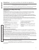
WARRANTY Thank You! ... for your purchase of a GE Brand appliance. Register Your Appliance: 5HJLVWHU \RXU QHZ DSSOLDQFH RQ OLQH DW \RXU FRQYHQLHQFH ZZZ JHDSSOLDQFHV FRP VHUYLFHBDQGBVXSSRUW UHJLVWHU Timely product registration will allow for enhanced communication and prompt service under the terms of your warranty, VKRXOG WKH QHHG DULVH
7U\ WKH *( $SSOLDQFHV :HEVLWH www.geappliances.
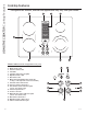
USING THE COOKTOP: Cooktop Features Cooktop Features Throughout this manual, features and appearance may vary from your model. 1 4 5 6 2 3 7 8 Feature Index (Features and appearance may vary) 1. 2. 3. 4. 5. 6. 7. 8. Left Rear Surface Unit Bridge Surface Unit Left Front Surface Unit Vent Grille Vent Filter (below the vent grille) Right Rear Surface Unit Dual Surface Unit Model and Serial Number Label (under the cooktop, on the right side of the vent chamber) 9. Left Rear Surface Unit Control 10.
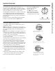
Radiant Surface Units The control for the radiant surface unit can be set anywhere between LO and HI for an unlimited number RI KHDW VHWWLQJV :LWK WKH LQILQLWH VZLWFK WKH FRLO F\FOHV RQ and off to maintain your selected control setting. To bring liquids to a boil faster, use a lid to cover the pan. The control knob must be pushed down and turned from the OFF SRVLWLRQ :KHQ WKH FRQWURO NQREV DUH LQ any position other than off, they may be turned without pushing down.
USING THE COOKTOP: Surface Burners Surface Burners (Cont.) Dual Surface Unit The right front surface unit has 2 cooking sizes to select from so you can match the size of the unit to the size of the cookware you are using. 7R XVH WKH ODUJH LQFK VXUIDFH XQLW WXUQ WKH NQRE clockwise to and select the desired setting. The unit will heat the entire area contained by the larger circle. 7R XVH WKH VPDOO LQFK surface unit, turn the knob counterclockwise to and select the desired setting.
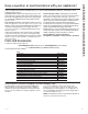
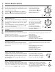
The following information will help you choose cookware which will give good performance on glass cooktops. Stainless Steel: Porcelain Enamel on Steel: recommended not recommended Heating empty pans can cause permanent damage to cooktop glass. The enamel can melt and bond to the ceramic cooktop. Aluminum: heavy weight recommended Good conductivity.
CARE AND CLEANING: Cleaning The Cooktop Cleaning The Cooktop Vent Grille %HIRUH FOHDQLQJ WKH YHQW JULOOH EH VXUH WKH H[KDXVW blower is turned off. To clean the vent grille, remove it from the cooktop by OLIWLQJ LW XS DQG RII :LSH ZLWK D GDPS FORWK ,I QHFHVVDU\ the vent grille can be washed in the sink. 8VH GLVKZDVKLQJ OLTXLG IRU FOHDQLQJ 'R QRW XVH DEUDVLYH FOHDQHUV They will damage the vent grille’s finish. 'R QRW FOHDQ WKH YHQW JULOOH LQ the dishwasher.
Normal Daily Use Cleaning 21/< XVH &(5$0$ %5<7(® &HUDPLF &RRNWRS &OHDQHU RQ WKH JODVV FRRNWRS 2WKHU FUHDPV PD\ QRW be as effective. To maintain and protect the surface of your glass FRRNWRS IROORZ WKHVH VWHSV %HIRUH XVLQJ WKH FRRNWRS IRU WKH ILUVW WLPH FOHDQ LW ZLWK &(5$0$ %5<7(® &HUDPLF &RRNWRS &OHDQHU This helps protect the top and makes cleanup easier. 'DLO\ XVH RI &(5$0$ %5<7(® &HUDPLF &RRNWRS &OHDQHU ZLOO KHOS NHHS WKH FRRNWRS ORRNLQJ QHZ 3.
CARE AND CLEANING: Cleaning the Glass Cooktop 12 Cleaning the Glass Cooktop Metal Marks and Scratches % H FDUHIXO QRW WR VOLGH SRWV DQG SDQV DFURVV \RXU FRRNWRS ,W ZLOO OHDYH PHWDO PDUNLQJV RQ WKH FRRNWRS surface. These marks are removable using the &(5$0$ %5<7(® &HUDPLF &RRNWRS &OHDQHU ZLWK WKH &(5$0$ %5<7(® &OHDQLQJ 3DG IRU &HUDPLF &RRNWRSV , I SRWV ZLWK D WKLQ RYHUOD\ RI DOXPLQXP RU FRSSHU are allowed to boil dry, the overlay may leave black discoloration on the cooktop.
Radiant Downdraft Cooktop PP9830 “If you have questions, call 800.GE.CARES or visit our website at: GEAppliances.com” BEFORE YOU BEGIN Read these instructions completely and carefully. • • IMPORTANT – Save these instructions for local inspector’s use. IMPORTANT – Observe all governing codes and ordinances. • Note to Installer – Be sure to leave these instructions with the Consumer. • Note to Consumer – Keep these instructions for future reference.
INSTALLATION INSTRUCTIONS Installation Instructions UNPACKING YOUR COOKTOP Check to be sure that all packing materials and tape have been removed. This will include tape on control knobs (if applicable), adhesive tape, wire ties, cardboard and protective plastic. Failure to remove these materials could result in damage to the appliance once the appliance has been turned on and surfaces have heated.
PREPARATION TOOLS AND MATERIALS YOU WILL NEED ELECTRICAL REQUIREMENTS • Cut resistant gloves • Saw • Flat-blade screwdriver • Electrician’s pliers • Duct tape • Measuring tape or scale • Carpenter’s square • 7/16” wrench or socket set • Drill and drill bit • Sheet metal screws • Junction box* • 3/4” flexible conduit* • Electrical wire per local code* • Wire nuts* • Ductwork *NOTE: Electrical installation kit JXCK89 may be ordered separately and includes all the parts necessary to connect the cooktop to ty
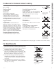
INSTALLATION INSTRUCTIONS Installation Instructions CABINET PREPARATION 1 PREPARING FOR INSTALLATION Positioning the cooktop The cooktop is designed to look best when centered in a cabinet at least 30” wide. The exhaust vent beneath the cooktop must be located between wall studs or floor joists so that the ductwork may be installed properly. At least 6” must be allowed between side edges of the cooktop and adjacent walls. 13" max. depth of unprotected overhead cabinets 30" min.
CABINET PREPARATION CUTOUTS 4 PREPARING THE COUNTERTOP 5 PREPARING FOR DUCTWORK The countertop must have a deep flat surface to accommodate the cooktop and the vent. Countertops with a rolled front edge and backsplash may not provide the flat surface area required. 25” min. flat surface area required NOTE: Ductwork MUST be vented to outside. DO NOT vent into a wall, ceiling, crawlspace, attic or any concealed space. Cut hole in cabinet wall or floor as appropriate for your installation.
INSTALLATION INSTRUCTIONS Installation Instructions DESIGN INFORMATION 7 PREPARE FOR DUCTWORK Determine the best route for ductwork; it can be routed in a variety of ways depending on the kitchen layout. IMPORTANT: The downdraft air discharge outlet for this unit is ø µ [ µ UHFWDQJXODU 3ODQ GXFWLQJ DFFRUGLQJO\ Typical duct arrangement countertop series. Outside wall cabinet Inside wall cabinet To maximize the ventilation performance of the vent system: 1.
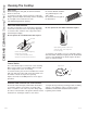
UNPACKING THE COOKTOP/INSTALLING THE GASKET 8 INSTALLING THE FOAM GASKET Do not install the cooktop into the countertop without installing the foam gasket as shown. It protects the bottom edge of the glass from the countertop and seals the cooktop against spills. Remove the cooktop along with its shipping pad from the shipping box. Remove the shipping block from the downdraft vent opening and place it under the shipping pad to provide level support.
INSTALLATION INSTRUCTIONS Installation Instructions INSTALLING THE COOKTOP 9 INSTALLING THE COOKTOP: CAUTION: DO NOT LIFT FROM VENT OPENING. INSTALLATION BRACKETS NOTE: Check for glass flatness in Step 9 before installing optional installation brackets. Optional installation bracket and thumbscrew (not included) Lift the cooktop by the glass side edges as shown. NOTE: Do not use the glass top vent opening to lift or move the cooktop into position.
INSTALLING THE COOKTOP 11 INSTALLING THE BLOWER PLENUM 12 INSTALLING THE BLOWER Slide the plenum, with the blower opening on the left, into the opening in the bottom of the cooktop. Push up on the plenum until the stops on the plenum contact the bottom of the cooktop, and snap the plenum into place. (You may have to move the plenum back and forth to work it into place.) Orient the blower discharge opening to match the ductwork in Steps 6 and 7.
INSTALLATION INSTRUCTIONS Installation Instructions INSTALLING THE COOKTOP 13 ATTACHING A BLOWER • Connect the 5-pin plug on the blower assembly to the matching 5-pin receptacle on the bottom of the cooktop. TRANSITION DUCT Use a blower transition duct for all downward duct installations to connect to 6” round standard ductwork. This 31ø4” x 10” rectangle to 6” round transition duct is available at your local building supply store.
ELECTRICAL CONNECTIONS 16 BEFORE MAKING ELECTRICAL CONNECTIONS Note to Electrician: The power leads supplied with this appliance are UL-recognized for connection to large gauge household wiring. The insulation of these leads is rated at temperatures much higher than the temperature rating of household wiring. The current carrying capacity of a conductor is governed by the wire gauge and also the temperature rating of the insulation around the wire.
INSTALLATION INSTRUCTIONS Installation Instructions ELECTRICAL CONNECTIONS 18 MAKING ELECTRICAL CONNECTIONS Effective January 1, 1996, the National Electrical Code requires that new, but not existing, construction utilize a four-conductor connection to an electric range. When installing an electric range in new construction, follow the instructions in NEW CONSTRUCTION AND FOURCONDUCTOR BRANCH CIRCUIT CONNECTION.
FINAL ASSEMBLY 19 INSTALL DOWNDRAFT FILTER VENT GRILLE Do not operate the vent without the filter in place. • Place the filter diagonally through the vent opening. Vent Filter Vent Chamber INSTALLATION INSTRUCTIONS Installation Instructions • Make sure it rests, at an angle, on the supports in the vent opening. • Carefully place the vent grille onto the downdraft opening. CHECK OPERATION OF DOWNDRAFT • Turn the vent fan speed control to HI, MED and LO to make sure all speeds operate correctly.
Notes 26 49-80635-1
Notes 49-80635-1 27
TROUBLESHOOTING TIPS Troubleshooting tips ... Before you call for service Save time and money! Review the charts on the following pages first and you may not need to call for service. Problem Possible Cause What To Do &RYHU SDQ ZLWK D OLG 7XUQ WKH GRZQGUDIW IDQ 2II until the water begins to boil. Water won’t boil Surface units will not maintain a rolling boil or cooking is slow Improper cookware being used.
radiante de ventilación descendente (downdraft) Estufa GEAppliances.com Información De Seguridad . . . . 2 Garantía . . . . . . . . . . . . . . . . . . . . . . . . . . 4 Asistencia / Piezas y Accesorios . . . . . . . . . . . . . 5 Manual del propietario e instalación PP9830 Uso de la placa de cocción Funciones de la Placa de Cocción . . . . 6 Quemadores . . . . . . . . . . . . . . . . . . . . . . . . 7 Utensilio para Placa de Cocción para Vidrio Radiante . . . . . . . . . . . . . . .
INFORMACIÓN DE SEGURIDAD INFORMACIÓN IMPORTANTE DE SEGURIDAD LEA TODAS LAS INSTRUCCIONES ANTES DE USAR ADVERTENCIA Lea todas las instrucciones de seguridad antes de utilizar este producto. No seguir estas instrucciones puede generar un incendio, una descarga eléctrica, lesiones corporales o la muerte.
PARA EVITAR LA PROPAGACIÓN DEL FUEGO: Ŷ 1R XWLOLFH DJXD HQ LQFHQGLRV GH JUDVD 1XQFD OHYDQWH XQDVDUWpQ HQ OODPDV $SDJXH ORV FRQWUROHV $SDJXH XQD VDUWpQHQ OODPDV VREUH XQD XQLGDG GH VXSHUILFLH FXEULHQGR OD VDUWpQ SRU FRPSOHWR FRQ XQD WDSD TXH DMXVWH ELHQ XQD SODQFKD SDUD JDOOHWDV R XQD EDQGHMD SODQD 8WLOLFH XQ TXtPLFR VHFR PXOWLXVR R XQ H[WLQWRU de incendios de espuma.
GARANTÍA ¡Gracias! ...
£&RQVXOWH HO 6LWLR :HE GH (OHFWURGRPpVWLFRV GH *( www.geappliances.
USO DE LA PLACA DE COCCIÓN: Funciones de la Placa de Cocción Funciones de la Placa de Cocción Es posible que las funciones y apariencias varíen con relación a su modelo a lo largo del manual. 1 5 6 2 3 7 8 Índice de características (las características y la apariencia podrían variar de acuerdo con su modelo) 1. 2. 3. 4. 5. 6. 7. 8. 9. 10. 11. 12. 13. 14. 15. 16. 17.
Unidades de superficie radiantes (O FRQWURO GH OD XQLGDG GH VXSHUILFLH UDGLDQWH SXHGH FRORFDUVH HQ FXDOTXLHU OXJDU HQWUH LO (Bajo) \ HI (Alto) SDUD XQ Q~PHUR de selecciones de calentamiento ilimitado.
USO DE LA PLACA DE COCCIÓN: Quemadores Quemadores (Cont.
/D VLJXLHQWH LQIRUPDFLyQ OR D\XGDUi D HOHJLU ORV UHFLSLHQWHV GH FRFFLyQ TXH EULQGDQ XQ EXHQ GHVHPSHxR HQ HVWXIDV GH YLGULR Acero inoxidable: Esmalte de porcelana sobre acero: 5HFRPHQGDGR No se recomienda &DOHQWDU UHFLSLHQWHV YDFtRV SXHGH SURYRFDU GDxRV SHUPDQHQWHV DO YLGULR GH ODV HVWXIDV (O HVPDOWH Verifique que los recipientes SXHGH GHUUHWLUVH \ DGKHULUVH D OD HVWXID FHUiPLFD tengan bases planas Aluminio: 6H UHFRPLHQGD GH FDSD JUXHVD %XHQD FRQGXFWLYLGDG /RV UHVLGXRV GH DOXPLQLR D YHFHV SDUHF
CUIDADO Y LIMPIEZA: Limpieza de la Placa de Cocción Limpieza de la Placa de Cocción Rejilla de ventilación $QWHV GH OLPSLDU OD UHMLOOD GH YHQWLODFLyQ DVHJ~UHVH GH TXH HO YHQWLODGRU GH VDOLGD HVWp DSDJDGR 3DUD OLPSLDU OD UHMLOOD GH YHQWLODFLyQ TXtWHOD GH OD HVWXID OHYDQWiQGROD KDFLD DUULED \ DIXHUD /tPSLHOD FRQ XQ SDxR K~PHGR 6L IXHUD QHFHVDULR OD UHMLOOD GH YHQWLODFLyQ SXHGH ODYDUVH HQ HO IUHJDGHUR 8WLOLFH OtTXLGR GH ODYDSODWRV SDUD ODYDU 1R XWLOLFH OLPSLDGRUHV DEUDVLYRV 'DxDUiQ HO DFDED
Limpieza normal de uso diario 6Ï/2 XWLOLFH HO OLPSLDGRU GH HVWXIDV FHUiPLFDV &(5$0$ %5<7(® HQ OD HVWXID GH YLGULR 2WUDV FUHPDV SXHGHQ QR VHU WDQ HIHFWLYDV 3DUD PDQWHQHU \ SURWHJHU OD VXSHUILFLH GH VX HVWXID GH YLGULR siga estos pasos: $QWHV GH XVDU OD HVWXID SRU SULPHUD YH] OtPSLHOD FRQ HO OLPSLDGRU GH HVWXIDV FHUiPLFDV &(5$0$ %5<7(® (VWR D\XGD D SURWHJHU OD HVWXID \ KDFH OD OLPSLH]D PiV VHQFLOOD (O XVR GLDULR GHO OLPSLDGRU GH HVWXIDV FHUiPLFDV &(5$0$ %5<7(® D\XGDUi D TXH OD HVWXID TXHGH
CUIDADO Y LIMPIEZA: Cómo Limpiar la Estufa de Vidrio 12 Cómo Limpiar la Estufa de Vidrio Marcas metálicas y rasguñaduras 7 HQJD FXLGDGR GH QR GHVOL]DU ROODV R VDUWHQHV D WUDYpV GH VX HVWXID (OODV GHMDUiQ PDUFDV VREUH OD VXSHUILFLH GH VX HVWXID (VWDV PDUFDV VRQ UHPRYLEOHV XVDQGR HO OLPSLDGRU GH HVWXIDV GH FHUiPLFD &(5$0$ %5<7(® con la almohadilla GH OLPSLDU HVWXIDV GH FHUiPLFD &(5$0$ %5<7(®.
Estufa radiante de ventilación descendente PP9830 “Si tiene alguna pregunta, llame al 800.GE.CARES o visite nuestro sitio Web en: GEAppliances.com” ANTES DE COMENZAR Lea estas instrucciones completa y cuidadosamente. • • IMPORTANTE – Guarde estas instrucciones para ser usadas por el inspector local. IMPORTANTE – Observe todos los códigos y ordenanzas aplicables. • Nota al instalador – Cerciórese de dejar estas instrucciones con el Consumidor.
INSTRUCCIONES DE INSTALACIÓN Instrucciones de Instalación DESEMPACANDO SU ESTUFA Asegúrese que todos los materiales de empaque y cintas se hayan retirado. Esto incluye cintas sobre las perillas de control (si corresponde), cinta adhesiva, cintas de ajuste, cartón y plástico protector. Si estos materiales no se retiran se puede producir como resultado un daño sobre el electrodoméstico, una vez que el mismo fue encendido y las superficies se calientan.
PREPARACIÓN HERRAMIENTAS QUE NECESITARÁ REQUISITOS ELÉCTRICOS • Guantes de protección contra cortes • Sierra • Destornillador plano • Alicates de electricista • Cinta adhesiva de conductos • Cinta métrica o escala • Escuadra de carpintero • Llave de 7/16" o juego de cubos • Taladradora y broca • Tornillos para hojas metálicas • Caja de unión* • Conducto flexible de 3/4"* • Cable eléctrico de acuerdo con los códigos locales* • Tuerca se alambre* • Conductos *NOTa: El Kit de instalación eléctrica JXCK89 pue
INSTRUCCIONES DE INSTALACIÓN Instrucciones de Instalación PREPARACIÓN DEL GABINETE 1 PREPARACIÓN PARA LA INSTALACIÓN Posición de su estufa La estufa está diseñada para lucir mejor cuando está centrada en un gabinete de por lo menos 30" de ancho. La ventanilla de escape debajo de la estufa debe estar localizada entre los bajantes de la pared o entre las vigas del piso de forma que el trabajo de tubos pueda ser instalado apropiadamente.
CORTES DE PREPARACIÓN DEL GABINETE 4 PREPARANDO LA ENCIMERA 5 PREPARACIONES PARA LOS CONDUCTOS La encimera debe tener una superficie plana profunda para acomodar la estufa y la ventilación. Las encimeras con un extremo frontal rodado y “backsplash” puede no proporcionar el área de superficie plana requerida. Área de superficie plana de un mínimo requerido de 25” NOTA: El trabajo de conductos DEBE tener ventilación hacia el exterior.
INSTRUCCIONES DE INSTALACIÓN Instrucciones de Instalación INFORMACIÓN SOBRE EL DISEÑO 7 PREPARACIÓN DEL CONDUCTO Determine el mejor recorrido para el conducto; el mismo puede ser conducido de diferentes formas dependiendo del esquema de la cocina. IMPORTANTE: La salida de la descarga de aire descendente para esta unidad es rectangular, y con una medida de 3 1/4” x 10”. Planifique el recorrido de forma consecuente. Serie de mesadas con distribución típica de tuberías.
CÓMO DESEMPACAR LA ESTUFA / INSTALAR LA JUNTA 8 CÓMO INSTALAR LA JUNTA DE ESPUMA No instale la estufa en la encimera sin haber instalado la junta de espuma como se muestra. Esta protege el extremo inferior del vidrio de la encimera y sella la estufa contra derrames. Remueva la estufa junto a sus almohadillas de empaque de la caja de envío. Remueva el bloque de envío de la abertura de ventilación descendente (downdraft) y colóquela debajo de la almohadilla de envío para proporcionar apoyo de nivel.
INSTRUCCIONES DE INSTALACIÓN Instrucciones de Instalación CÓMO INSTALAR LA ESTUFA 9 CÓMO INSTALAR LA ESTUFA PRECAUCIÓN: NO LEVANTE POR LA ABERTURA DE VENTILACIÓN. Levante la estufa por los extremos del lado del vidrio como se muestra. NOTA: No use la abertura de ventilación para levantar o INSTALACIÓN OPCIONALES NOTA: Verifique que el vidrio esté plano en el paso 9 antes de colocar los soportes de instalación opcionales.
CÓMO INSTALAR LA ESTUFA 11 CÓMO INSTALAR LA CÁMARA DEL 12 CÓMO INSTALAR LA CÁMARA Deslice la cámara, con la abertura del soplador del lado izquierdo, en la abertura en el fondo de la estufa. Empuje la cámara hasta que se detenga cuando la cámara haga contacto con el fondo de la estufa, y la cámara encaje en su lugar. (Es posible que usted tenga que mover la cámara hacia adelante y hacia atrás para encontrar su lugar exacto.
INSTRUCCIONES DE INSTALACIÓN Instrucciones de Instalación CÓMO INSTALAR LA ESTUFA 13 CÓMO PEGAR UNA TRANSICIÓN DE SOPLADOR Use un conducto de transición de soplador para todas las instalaciones de conductos de flujo de aire descendente para conectar las piezas de conducto de 6” redondas. Este rectángulo de 31ø4” x 10” a conducto de 6” redondo de transición está disponible en su ferretería local.
CONEXIONES ELÉCTRICAS 16 ANTES DE HACER CONEXIONES ELÉCTRICAS Nota al electricista: Los conductores proporcionados con este electrodoméstico son reconocidos por la UL para conexiones eléctricas residenciales de calibres altos. El aislamiento de estos conductores es considerado a temperaturas mucho mayores que las esperadas en residencias. La capacidad de carga actual de un conductor es determinado por el calibre del cable y también por la temperatura considerada del aislamiento alrededor del cable.
INSTRUCCIONES DE INSTALACIÓN Instrucciones de Instalación CONEXIONES ELÉCTRICAS 18 CÓMO HACER LAS CONEXIONES ELÉCTRICAS Efectivo el 1 de enero de 1996, el National Electrical Code requiere las construcciones nuevas, pero no ya existentes, utilicen conexiones de cuatro conductores para estufas eléctricos. Cuando se encuentre instalando una estufa eléctrica en una construcción nueva, siga las instrucciones en CONSTRUCCIÓN NUEVA Y CONEXIÓN DE RAMAL DE CIRCUITO DE CUATRO CONDUCTORES.
ENSAMBLAJE FINAL 19 CÓMO INSTALAR EL FILTRO DE FLUJO DOWNDRAFT Y LA PARRILLA DE VENTILACIÓN No opere la ventilación sin el filtro en su lugar. • Coloque el filtro diagonalmente a través de la abertura de ventilación. Filtro de ventilación Cámara de ventilación INSTRUCCIONES DE INSTALACIÓN Instrucciones de Instalación • Cerciórese de que el filtro descanse, en un ángulo, en los soportes de la abertura de ventilación.
Notas 26 49-80635-1
Notas 49-80635-1 27
CONSEJOS PARA LA SOLUCIÓN DE PROBLEMAS 28 Consejos para la Solución de Problemas... Antes de solicitar el servicio técnico ¡Ahorre tiempo y dinero! Primero revise los cuadros que aparecen en las siguientes páginas y es posible que no necesite solicitar reparaciones.