KITCHEN HUB™ SAFETY INFORMATION. . . . . . . . . . . . . .3 USING THE KITCHEN HUB Hardware . . . . . . . . . . . . . . . . . . . . . . . . . . . . . . . . .5 Control Features . . . . . . . . . . . . . . . . . . . . . . . . . . .5 Wi-Fi Connect . . . . . . . . . . . . . . . . . . . . . . . . . . . . 6 Chef Connect . . . . . . . . . . . . . . . . . . . . . . . . . . . . 6 OWNER’S MANUAL & INSTALLATION INSTRUCTIONS UVH1301 CARE AND CLEANING Filters . . . . . . . . . . . . . . . . . . . . . . . . . . . . .
THANK YOU FOR MAKING GE APPLIANCES A PART OF YOUR HOME. Whether you grew up with GE Appliances, or this is your first, we’re happy to have you in the family. We take pride in the craftsmanship, innovation and design that goes into every GE Appliances product, and we think you will too. Among other things, registration of your appliance ensures that we can deliver important product information and warranty details when you need them. Register your GE appliance now online.
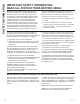
WARNING TO REDUCE THE RISK OF FIRE, ELECTRIC SHOCK OR INJURY TO PERSONS, OBSERVE THE FOLLOWING: A. Use this unit only in the manner intended by the manufacturer. If you have questions, contact the manufacturer. B. To avoid the risk of scald injury from a hot cooktop, keep young children away from the touchscreen. C. Before servicing or cleaning unit, switch power off at service panel and lock the service disconnecting means to prevent power from being switched on accidentally.
SAFETY INFORMATION IMPORTANT SAFETY INFORMATION READ ALL INSTRUCTIONS BEFORE USING NOTE: This equipment has been tested and found to comply with the limits for a Class B digital device, pursuant to part 15 of the FCC Rules. These limits are designed to provide reasonable protection against harmful interference in a residential installation.
Front Camera Screen LVYLOOH 25 °F | LRX 8:50 bruary Monday, Fe Speaker 12 Volume Button On/Off Swipe up on the screen to access controls. Recipes 1HWÀL[ Hulu ent Entertainm U+ Connect Music HV« 6SRWLI\ Skype Google n Blue Apro 3OD\ 0RYL Cooktop Camera Lights Control Features 3 4 1 5 7 8 FAN OFF LOW MED 9 LIGHT HIGH BOOST OFF 2 DIM HIGH 6 1. Ventilation Fan and Light Control Screen 6. 2. FAN: Speed control for fan. Tap LOW for LOW speed.
USING THE KITCHEN HUB: WiFi / Heat Sensor / Screen Moisture Protection 6 USING THE KITCHEN HUB Connecting your WiFi Connect Enabled Appliance Your GE Appliances Kitchen Hub is recommended to be connected to WiFi. Use the Setup Wizard to connect unit to WiFi. Heat Sensor This unit is equipped with a heat sensor that will activate the ventilation FAN if excessive temperatures are detected above the cooktop surface to protect the Kitchen Hub components from overheating.
Be sure the circuit breaker is off and all surfaces are cool before cleaning or servicing any interior part of the unit. Metal Grease Filter The metal filters trap grease during cooking. The filters must ALWAYS be in place when the unit is in use. The grease filters are dishwasher-safe and should be cleaned every month, depending on the usage of the unit. To remove: Press on the filter handle to disengage the filter lock to release the filter.
CARE AND CLEANING: Surfaces Surfaces Stainless Steel Surfaces (on some models) Do not use a steel wool pad; it will scratch the surface. Use only a liquid cleanser free of grit and rub in the direction of the brush lines with a damp soft sponge. To clean the stainless steel surface, use warm sudsy water or a stainless steel cleaner or polish. Always wipe the surface in the direction of the brush line. Follow the cleaner instructions for cleaning the stainless steel surface.
Kitchen Hub UVH1301 “If you have questions, call GE Appliances at 800.GE.CARES (800.432.2737) or visit our website at: GEAppliances.com” BEFORE YOU BEGIN Read these instructions completely and carefully. Ŷ IMPORTANT — Save these instructions for local inspector’s use. Ŷ IMPORTANT — Observe all governing codes and ordinances. Ŷ Note to Installer – Be sure to leave these instructions with the Consumer. Ŷ Note to Consumer – Keep these instructions for future reference.
INSTALLATION INSTRUCTIONS Installation Instructions IMPORTANT SAFETY INSTRUCTIONS GROUNDING INSTRUCTIONS This appliance must be grounded. In the event of an electrical short circuit, grounding reduces the risk of electric shock by providing an escape wire for the electric current. This appliance is equipped with a cord having a grounding wire with a grounding plug. The plug must be plugged into an outlet that is properly installed and grounded.
MOUNTING SPACE Ǝ max. òƎ Ǝ Ǝ Ǝ PLQ IURP the floor to the bottom of the cabinet. 69" is the recommended distance. Ǝ min. Bottom edge of cabinet needs WR EH Ǝ RU more from the cooking surface or top surface of gas grates, whichever is taller Backsplash NOTES: 7KH VSDFH EHWZHHQ WKH FDELQHWV PXVW EH Ǝ ZLGH and free of obstructions. • If you are going to vent your unit to the outside, see Installation Types 2A or 2C for cabinet and wall preparation.
INSTALLATION INSTRUCTIONS Installation Instructions TOOLS AND MATERIALS REQUIRED (NOT SUPPLIED) PARTS NEEDED FOR INSTALLATION Ŷ 1 Wall or Roof Cap (for ducted venting only) Ŷ All Metal Ductwork (for ducted venting only) Safety glasses Pencil and tape measure Phillips screwdriver Level Rectangular duct and adaptors as needed per installation (length will vary) Aluminized duct tape DAMAGE – SHIPMENT/INSTALLATION • If the unit is damaged in shipment, return the unit to the store in which it was bought fo
PARTS INCLUDED ADVANCE PLANNING ADDITIONAL PARTS Duct Install Planning (for outside exhaust only) Ŷ 8VH PHWDO GXFWZRUN RQO\ PART ≤ ≤ ≤ QUANTITY Top Cabinet Template 1 Rear Wall Template 1 Owner's Manual 1 Exhaust Adaptor Charcoal Filter Ŷ 'HWHUPLQH WKH H[DFW ORFDWLRQ RI WKH DSSOLDQFH Ŷ 3ODQ WKH URXWH IRU YHQWLQJ H[KDXVW WR WKH RXWGRRUV To maximize the ventilation performance of the vent system: 1 2 1. Minimize the duct run length and number of transitions and elbows. 2.
INSTALLATION INSTRUCTIONS Installation Instructions 1. PLACEMENT OF THE MOUNTING PLATE A REMOVING THE KITCHEN HUB FROM THE CARTON/REMOVING THE MOUNTING PLATE B FINDING THE WALL STUDS Remove the packaging CAUTION Wear gloves to protect against Wall Studs sharp edges. 1. Open the box and fold back all four carton flaps fully against the carton sides. Remove the following items from the protective foam: charcoal filters, cord plug, damper, and screws.
1. PLACEMENT OF THE MOUNTING PLATE (Cont.
INSTALLATION INSTRUCTIONS Installation Instructions 1. PLACEMENT OF THE MOUNTING PLATE (Cont.) D ALIGNING THE MOUNTING PLATE 30” Hole B Draw a Vertical Line on Wall from Center of Top Cabinet Hole A Hole D Hole C Area E Notch CAUTION Wear gloves to protect against sharp edges. 1. Draw a vertical line on the wall at the center of the Ǝ ZLGH VSDFH 2. Use the mounting plate as the template for the rear wall.
2. INSTALLATION TYPES This appliance is designed for adaptation to the following 3 types of ventilation: A. Outside Top Exhaust (Vertical Duct) (Choose A, B or C) NOTE: Select the type of ventilation required for your installation and proceed to that section. This unit is shipped assembled for outside top exhaust. B. Recirculating (Non-Vented Ductless) C. Outside Back Exhaust (Horizontal Duct) A OUTSIDE TOP EXHAUST B RECIRCULATING (VERTICAL DUCT) (NON-VENTED DUCTLESS) See page 18. See page 21.
INSTALLATION INSTRUCTIONS Installation Instructions A. OUTSIDE TOP EXHAUST (Vertical Duct) INSTALLATION OVERVIEW A1. Attach Mounting Plate to Wall A2. Prepare Top Cabinet A3. Adjust Blower Exhaust A4. Install Exhaust Adaptor A5. Mount the Kitchen Hub A6. Connect Ductwork A7. Finalize Installation A1 ATTACH THE MOUNTING PLATE TO THE WALL B A A1 ATTACH THE MOUNTING PLATE TO THE WALL (Cont.) CAUTION Be careful to avoid pinching fingers between the back of the mounting plate and the wall. 4.
A. OUTSIDE TOP EXHAUST A3 ADJUST BLOWER EXHAUST The unit is shipped in the top exhaust configuration. If configuration is not in the top exhaust direction, follow the steps below. CAUTION Wear gloves to protect against (Vertical Duct) (Cont.) A4 ASSEMBLE AND INSTALL ADAPTOR Screws Damper sharp edges. 1. Remove damper mounting plate and diverter. 2. Remove diverter from angled position and reinsert vertically as shown. 3. Reattach the damper mounting plate with opening on top of unit as shown.
INSTALLATION INSTRUCTIONS Installation Instructions A. OUTSIDE TOP EXHAUST A5 MOUNT THE KITCHEN HUB (Vertical Duct) (Cont.) A5 MOUNT THE KITCHEN HUB (Cont.) 3. Insert 2 self-aligning screws(1/4" - 28 x 3-1/4") through top-center cabinet hole. Turn two full turns on each screw. Cabinet Front Cabinet Bottom Shelf Filler Block CAUTION To avoid the risk of personal injury (back injury or other injuries due to excessive weight of the unit) or property damage, you will need two people to install this product.
A. OUTSIDE TOP EXHAUST A6 CONNECTING DUCT WORK 1. Extend the house duct down to connect to the exhaust adaptor. 2. Seal exhaust duct joints using duct tape. (Vertical Duct) (Cont.) INSTALLATION INSTRUCTIONS Installation Instructions A7 FINALIZE INSTALLATION Plug in the unit. 49-2000492 Rev.
INSTALLATION INSTRUCTIONS Installation Instructions B. RECIRCULATING (Non-Vented Ductless) INSTALLATION OVERVIEW B1. Attach Mounting Plate to Wall B2. Prepare Top Cabinet B3. Adjust Blower Exhaust B4. Mount the Kitchen Hub B5. Filters B6. Finalize Installation B1 ATTACH THE MOUNTING PLATE TO THE WALL B1 ATTACH THE MOUNTING PLATE TO THE WALL (Cont.) CAUTION Be careful to avoid pinching fingers between the back of the mounting plate and the wall. 4. Tighten all bolts.
B3 ADJUST BLOWER EXHAUST B4 MOUNT THE KITCHEN HUB The unit is shipped in the top venting mode exhaust configuration. The vertical deflector plate should be repositioned to the angled position. 1. Remove damper mounting plate and diverter. CAUTION To avoid the risk of personal injury (back injury or other injuries due to excessive weight of the unit) or property damage, you will need two people to install this product. IMPORTANT: Do not put any pressure on front screen during installation.
INSTALLATION INSTRUCTIONS Installation Instructions B. RECIRCULATING (Non-Vented Ductless) (Cont.) B4 MOUNT THE KITCHEN HUB (Cont.) ,QVHUW VHOI DOLJQLQJ VFUHZV » Ǝ [ through outer top cabinet holes. Turn two full turns on each screw. B5 FILTERS 1. Remove grease filter and install a charcoal filter on each side of the motor as shown below.
C. OUTSIDE BACK EXHAUST (Horizontal Duct) INSTALLATION OVERVIEW C1. Prepare Rear Wall C2. Attach Mounting Plate to Wall C3. Prepare Top Cabinet C4. Adjust Blower Exhaust C5. Mount the Kitchen Hub C6. Finalize Installation C1 PREPARING THE REAR WALL FOR OUTSIDE BACK EXHAUST You need to cut an opening in the rear wall for outside exhaust. C2 ATTACH THE MOUNTING PLATE TO THE WALL (Cont.) 1. Remove the toggle wings from the bolts. 2.
INSTALLATION INSTRUCTIONS Installation Instructions C. OUTSIDE BACK EXHAUST C3 USE TOP CABINET TEMPLATE FOR PREPARATION OF TOP CABINET You need to drill holes for the top support screws and a hole large enough for the power cord to fit through. (Horizontal Duct) (Cont.) C4 ADJUST BLOWER EXHAUST The unit is shipped in the top exhaust configuration. To adjust the unit to back exhaust remove damper mounting plate and reposition such that opening is in the back of the unit.
C. OUTSIDE BACK EXHAUST C6 MOUNT THE KITCHEN HUB CAUTION To avoid the risk of personal injury (back injury or other injuries due to excessive weight of the unit) or property damage, you will need two people to install this product. IMPORTANT: Do not put any pressure on front screen during installation. (Horizontal Duct) (Cont.) C6 MOUNT THE KITCHEN HUB (Cont.) 2. Rotate front of unit up against cabinet bottom. 3. Insert 2 self-aligning screws (1/4”-28 x 3-1/4”) through top-center cabinet hole.
TROUBLESHOOTING TIPS Installation Instructions MAKE UP AIR TECHNOLOGY Note to Installers and Inspectors: This product comes equipped with a simple installation feature that limits maximum CFM levels in order to comply with certain local codes or regulations. This installation method may not be necessary for all installations, please refer to your local codes for further guidelines. CAUTION Appliance must be disconnected from main power prior to performing the conversion instructions listed below.
Save time and money! Review the charts on the following pages first and you may not need to call for service. Problem Possible Cause What To Do Fan/Light does not operate when button is turned ON A house fuse may be blown or a circuit breaker tripped. Replace fuse or reset circuit breaker. Loud or abnormal airflow noise Wrong duct size used in installation. This unit requires 8” ducting to perform optimally. Using smaller duct pipe will cause reduced venting.
LIMITED WARRANTY GE Appliances Limited Warranty GEAppliances.com All warranty service is provided by our Factory Service Centers, or an authorized Customer Care® technician. To schedule service online, visit us at geappliances.com/service_and_support/, or call GE Appliances at 800.GE.CARES (800.432.2737). Please have your serial number and your model number available when calling for service. Servicing your appliance may require the use of the onboard data port for diagnostics.
Looking For Something More? GE Appliances offers a variety of accessories to improve your cooking and maintenance experiences! Refer to the Consumer Support page for phone numbers and website information. The following products and more are available: Parts Make-up Air Kit ACCESSORIES Accessories Charcoal Filter Bump Out Kit Filler Kit Cleaning Supplies CitruShine™ Stainless Steel Wipes CERAMA BRYTE® Stainless Steel Appliance Cleaner Bar Keepers Friend Soft Cleanser™ 49-2000492 Rev.
CONSUMER SUPPORT Consumer Support GE Appliances Website Have a question or need assistance with your appliance? Try the GE Appliances Website 24 hours a day, any day of the year! You can also shop for more great GE Appliances products and take advantage of all our on-line support services designed for your convenience. In the US: GEAppliances.