E4H-CE AND E8-CE SERIES WATER PURIFICATION MACHINES 3 m3/hr to 45 m3/hr 18,000 gpd to 288,000 gpd Operation and Maintenance Manual
INSTRUCTIONS FOR E4H-CE AND E8-CE WATER PURIFICATION OPERATION AND MAINTENANCE MANUAL TABLE OF CONTENTS Page 1.0 DESCRIPTION 1 1.1 1 1 1 1 1 2 2 2 2 2 3 3 3 5 5 7 8 8 8 8 9 1.2 1.3 1.4 2.0 3.0 Definitions 1.1.1 Permeate Rate 1.1.2 Concentrate Rate 1.1.3 Feed Rate 1.1.4 Reverse Osmosis 1.1.5 Membrane Elements 1.1.6 Clean-In-Place 1.1.7 Flow Control Center 1.1.8 Average Pressure 1.1.9 Concentration 1.1.10 Salt (Ionic) Passage 1.1.11 Recovery 1.1.
Page 4.0 5.0 MACHINE OPERATION AND MAINTENANCE 17 4.1 4.2 4.3 4.4 4.5 4.6 17 17 17 19 19 21 Daily Log Sheets Pre-Filter Cartridge Cleaning Draining Machine for Shipment Membrane Element Replacement Membrane Element Removal FIELD INSTALLED ACCESSORIES 22 5.1 5.2 5.3 5.4 22 22 24 24 Pretreatment Shutdown Permeate Flush Chemical Pump Clean-In-Place Installation 6.0 TROUBLESHOOTING 25 7.0 FORMS 33 7.1 7.2 7.3 33 34 35 8.
Page LIST OF FIGURES Figure Title 1.1 1.2 1.3 Normal Versus Cross Flow Filtration Membrane Element With Interconnectors Principles of Operation 1 2 3 LIST OF TABLES Figure Title 1.1 1.2 1.3 2.4 2.
1.0 DESCRIPTION E-CE Series Reverse Osmosis (RO) machines are durable pieces of equipment, which, with proper care, will last for many years. These instructions give operation and maintenance details vital to the sustained performance of the machine. Please read completely before operating your machine. 1.1 Definitions The operating definitions provided below will help you further understand your machine and this manual. 1.1.
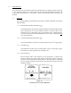
1.1.5 Membrane Elements Membrane elements are interleaved layers of semi-permeable membrane, spacer, and permeate carrier spiraled around a central permeate tube make up the membrane element. Figure 1.2 Membrane Element with Interconnectors 1.1.6 Clean-In-Place The abbreviation for Clean-In-Place is CIP. 1.1.7 Flow Control Center The Flow Control Center features a concentrate flow control valve, a recycle flow control valve, and a pressure gauge. It is located directly behind the control enclosure. 1.
Cf = Feed Concentration Cp = Permeate Concentration Cc = Concentrate Concentration Cavg = Average Concentration in Machine 1.1.10 Salt (Ionic) Passage Ionic Salt Passage equals the percent of dissolved salts passed through the membrane element or 100% minus rejection. 1.1.11 Recovery Recovery equals permeate rate divided by feed rate and is expressed as a percentage. For example, 75% recovery means that out of a given feed rate, 75% is produced as purified water (permeate). 1.1.
Rejection Passage Recovery 4 = [(Cavg) - (CP)] x 100 (Cavg) = [(237.5 mg/L) + (8.3 mg/L)] x 100 (237.5) = 96.5% = (CP) x 100 (Cf) = (8.3 mg/L) x 100 (237.5) = 3.
1.
· · Multi-stage centrifugal pump, SS construction (SS end castings and wetted parts, Noryl* internals) on the 3 to 3 to 34m3/hr and AS (all Stainless Steel components) on the 45m3/hr. Electrical package includes Programmable Logic Controller (PLC), IEC66 control enclosure with a 24VDC control circuit, Siemens TP070 operator interface terminal, and a Siemens S7-200 PLC.
1.4 Specifications for E-CE Series Machines The machine flow specifications listed, Table 1.1 below, are based on 25°C (77°F) and 2000 ppm NaCl. Table 1.1 Flow Specifications for Reverse Osmosis E-CE Machines MODEL E4H-CE-3 E4H-CE-% E4H-CE-7 E4H-CE-9 E4H-CE-14 E4H-CE-23 Recovery 50-75% 50-75% 50-75% 66-75% 66-75% 66-75% Units LPM/GPM LPM/GPM LPM/GPM LPM/GPM LPM/GPM LPM/GPM Permeate Rate 47.4/12.5 78.9/20.9 126.3/33.4 151.4/40.0 227.1/60.0 378.5/100.
1.4.1 Feed Water Specifications The feed water requirements listed in Table 1.1 must be met to ensure quality permeate and extended membrane element life. 1.4.2 Permeate Flow Rate Stated in Table 1.1 and on the machine serial number label (assumes no permeate back pressure, 2000 mg/L Total Dissolved Solids (TDS) maximum feed concentration, and rated temperature). To estimate permeate output with back pressure, use the formula below. Maximum permeate back pressure is 80 psig (5.5 bar).
1.4.5 Reverse Osmosis Membrane Element Rejection E8-CE RO machines use Fiberglass Reinforced Plastic (FRP). E4H-CE RO machines use tape wrapped membrane elements. For more information, refer to the Spare Parts List (P/N 1233377). Table 1.3 Membrane Element Specifications Specification E4H-CE E8-CE Outer Cover Material Tape FRP Typical Ionic Rejection (TDS) 98.0 - 99.5% 98.0 - 99.5% Nominal Permeate Flow Rate [at 7.6 bar (110 psi)] 8.3 m3/d (2200 gpd) 39.
2.0 INSTALLATION The following installation guidelines will help you install your new E-CE RO machine. 2.1 Feed Water Requirements The following feed water requirements must be met before installing your new E-CE RO machine to ensure quality permeate and extended membrane element life. Table 2.4 Feed Water Requirements Temperature Typical: 10 - 29°C (50° - 85°F) Inlet Pressure Minimum: 2.1 barg (30 psig) Maximum: 4.
membrane element housings for removal and loading of membrane elements. If 114 cm (45-inches) are not available, the entire membrane element housing may need to be removed for membrane element replacement. 2.3 Plumbing The E4H-CE and E8-CE come with flanged connections installed on all isolation valves. Table 2.5 Connections 2.
3.0 PREPARATION AND START-UP 3.1 Pretreatment for Water Purification All systems will operate most efficiently on filtered water with a pH of less than 6.5 and a Silt Density Index (SDI) of 5 or below. If the machine is operated on higher pH water, other forms of pretreatment may be necessary. A water analysis prior to start-up of the machine is required.
STEPS 1. Recheck the function and integrity of your pretreatment equipment. Ensure that your water softener, activated carbon filters, and iron filters (where applicable) have been leaked checked, back washed, and thoroughly rinsed for service before starting up your RO unit. 2. Attach the feed water pipe to the inlet of the machine. The standard connection fitting is a polyvinyl chloride (PVC) flanged connection. Refer to Table 2.5 (Connections) for connection sizes. 3.
It is also important to understand the relationship of these two valves, the pressure gauge, and your RO pump. The pump has a fixed amount of flow produced, and the valves are the control devices to distribute this fixed flow amount. The pressure gauge is an indicator of applied membrane element pressure a the flows set by the valves 8. Press the Fill Button on the OIT so it is in the ON position. Water should begin to flow through the machine at this point, but the pump will not start.
15. As the machine purges the air and fills with water, the pressure will gradually increase. Water should flow through the permeate and concentrate piping, viewed on the individual flow meters. If you do not see flow, turn the machine OFF and return to Section 3.2 (Initial Start-Up). 16. Gradually adjust the concentrate flow control valve. As you adjust the valve, watch the average pressure (Pavg) and the your concentrate flow meter.
3.3 Daily Start-Up Check the machine to insure isolation valves are in the proper positions for operation. To turn the RO ON, press the RO button so it is in the ON position. If the alarm light is lit, push the “Alarm Reset” switch on the control enclosure and the alarm button on the OIT. If the alarm light stays lit, check the RO for an alarm condition. Otherwise, the main inlet valve will open, and the high-pressure pump will turn on.
4.0 MACHINE OPERATION AND MAINTENANCE The operation and maintenance of a E-CE RO Series machine is relatively simple, but requires regular data recording and routine preventative maintenance. It cannot be emphasized enough the importance of filling out the Daily Log Sheet (Section 7.3) during each operating shift. A StartUp Data Sheet was completed at start-up (Section 7.2) containing pertinent facts on the operation of your machine.
flow and/or rejection of salts, or an increased pressure drop across the machine will indicate when cleaning is required. GE Osmonics recommends cleaning at least every month to assure good membrane element performance and long membrane element life. GE Osmonics offers a full line of chemical cleaners for specific cleaning needs. Refer to the Spare Parts List (P/N 1233377). To clean membrane elements: STEPS 1. The E-CE RO machines do not include a Clean-In-Place (CIP) pump.
reestablish normal operation. Operate the machine as described in the flushing section for at least one hour. The detergent is sufficiently flushed when the permeate conductivity is restored to its normal previous level. When conductivity is back to normal, divert the permeate and concentrate back to service positions. 4.
2. Cut the bag open as close as possible to the seal at the end of the bag, so that the bag may be reused if necessary. 3. Remove the membrane element from the bag and remove the foam protectors from each end of the membrane element. 4. Remove the parts from the parts container (if included) and inspect. Make sure all parts are clean and free of dirt. Examine the O-rings, brine seal, and permeate tube for nicks or cuts. Replace the O-rings or brine seal, if damaged.
4.6 Membrane Element Removal As time progresses, the efficiency of the membrane element will be reduced. In general, the salt rejection does not change much until two or three years after installation, when operated on properly pretreated feed water and routine maintenance performed. The permeate flow rate will begin to decline slightly after one year of operation, but can be extended with diligent flushing and cleaning of the machine.
5.0 FIELD INSTALLED ACCESSORIES 5.1 Pretreatment Shutdown E-CE Series RO machines are equipped with Pretreatment Shutdown control capability. Pretreatment Shutdown is the ON/OFF control of the RO via a signal from a remote device. External Control can be used when Permeate Flush is not desired prior to RO shutdown (Permeate Flush, Section 5.2). The Permeate Shutdown control could be remote ON/OFF, level control, pretreatment lockout, and/or post-treatment lockout, etc.
centration of the diluted feed stream, at the operating recovery, is that the water in the machine at shutdown will have total dissolved solids (TDS) concentrations approximately equal to the machine feed TDS level. The low TDS environment created reduces the potential for membrane element fouling during the down period, extending membrane element life. The purge operates for a ten (10) minute period.
4. Turn the AUTO/HAND Button on the Purge Button located on the OIT to the “AUTO” position. With multiple remote devices wired in series, as described above, an open contact from any of the configured devices will activate the Permeate Purge Cycle. 5.3 Chemical Pump GE Osmonics offers a stand-alone chemical pump and tank that can be used to control the pH of the RO system. Refer to the Spare Parts List (P/N 1233377) for ordering information. 5.
6.0 TROUBLESHOOTING This troubleshooting guide can assist you in identifying common operating problems you may experience with your machine. The operator can easily correct many of these problems, however, for those that persist or are not understood you should contact the GE Osmonics Customer Support Center. Have the following information available when calling the Customer Support Center: 1. 2. 3. 4.
TROUBLESHOOTING SYMPTOM POSSIBLE CAUSES Low operating pressure (continued) Insufficient electrical power Check the fuses or circuit breakers; measure the voltage. Pump not operating correctly See Tonkaflo pump instructions. Low operating pressure See possible causes for low pressure. Dirty or fouled membrane elements Flush and clean the membrane elements. Operating on cold water less than 13°C (55°F) Install a hot/cold feed water tempering valve if more permeate flow is needed.
TROUBLESHOOTING SYMPTOM POSSIBLE CAUSES Low permeate flow rate (continued) Operating on cold water less than 13°C (55°F) Install a hot/cold feed water tempering valve if more permeate flow is needed. Operate with a feed water temperature of 22° - 25°C (72° -77°F). Membrane elements installed backward or damaged concentrate seal Install membrane elements in the direction of fluid flow. Flush and clean the machine immediately.
TROUBLESHOOTING SYMPTOM POSSIBLE CAUSES High operating pressure Recycle or concentrate valve plugged Disassemble the plumbing to the recycle valve and remove foreign particles. Check the concentrate valve stem. Inaccurate pressure gauge Replace or calibrate the gauge as required. Restricted flow after pump outlet Check for blockage of the concentrate flow at the inlets and outlets of the membrane element housings.
TROUBLESHOOTING SYMPTOM POSSIBLE CAUSES Declining rejection (high permeate conductivity) (continued) O-ring seal broken or damaged Replace O-ring, check the sealing surfaces on the O-ring groove, interconnectors and end caps. Replace damaged parts. Change in incoming water quality Open the concentrate valve and flush. Test the water for pH, hardness, TDS, and iron content. A water analysis should be sent to GE Osmonics for review.
TROUBLESHOOTING SYMPTOM POSSIBLE CAUSES REMEDIES Machine not operating (continued) Thermal overload in motor has tripped Allow the machine to cool: check the feed water supply and/or amp draw to the motor. No power to machine Check the fuses or circuit breakers, measure the voltage. Motor and/or pump not operating properly See Tonkaflo pump instructions. Contact GE Osmonics for possible repair or replacement.
TROUBLESHOOTING SYMPTOM POSSIBLE CAUSES REMEDIES Electrical machine shut down (continued) Motor starter overloaded, heater tripped. Turn the switch OFF; let the heater(s) cool. Conductivity drifts or changes after calibration Calibration may have been done before the reading stabilized When calibrating, wait at least 15 seconds to 1-1/2 minutes for reading to stabilize.
TROUBLESHOOTING SYMPTOM POSSIBLE CAUSES Chemical pump will not feed chemical Pumping may be affected by other software variables Is the relay turned ON or OFF? Is the CIP input activated? You must have permeate or concentrate flow for a relay configured as a set point to function and trigger the pump. Chemical pump feed reverse of what you expected Relay set point not properly configured Determine whether you need the relay configured for direct or reverse set point feed.
7.0 FORMS 7.1 RETURN GOODS AUTHORIZATION (RGA) If you wish to return goods for repair, warranty evaluation and/or credit, please have your original sales order or invoice available when you call GE Osmonics. Call GE Osmonics at (800) 848 - 1750 and ask to speak with Customer Service. A GE Osmonics Customer Service representative will provide instructions and a return goods authorization number, which needs to be clearly written on the outside of the box used to ship your materials.
7.
PRESSURE CONCENTRATE (BLOW-BY) Qc PERMEATE (PURE WATER) Qp RESISTANCE TEMPERATURE RECYCLE CONDUCTIVITY 35 OPERATOR’S INITIALS This is a template. Make copies as needed. *Symbols: Q - Flow Rate; C - Conductivity Reference the Troubleshooting Guide in your Instruction Manual where trends or differences are noted. SERIAL NO.: NOTE: PERIOD OF THIS SHEET MACHINE MODEL NO.: © Copyright 2003, GE Osmonics, Inc. Printed in USA, P/N Rev.
8.0 WARRANTY 8.1 Warranty Terms Subject to the terms and conditions set forth hereinafter, Seller (GE Osmonics, Inc.
discretion, be the sole judge of whether a returned product or component is defective in material or workmanship. Required or replaced products or components shall be returned freight. In genuine emergency situation, Seller will (at Seller’s sole option) forward replacement parts to Buyer without waiting for authorized return of the questionable part(s). In such cases, Buyer will issue a purchase order or other payment guarantee prior to shipment.
NO WARRANTY OR OTHER LIABILITY OF SELLER TO BUYER UNDER THIS AGREEMENT OR OTHERWISE WILL IN ANY EVENT EXCEED THE COST OF REPLACEMENT OF THE APPLICABLE SELLER PRODUCT, PART, OR ACCESSORY THAT IS SUBJECT TO ANY BREACH OF SELLER’S WARRANTY. SELLER WILL NOT BE LIABLE FOR ANY DAMAGE TO ANY PROPERTY OF BUYER OR TO BUYER’S CUSTOMERS FOR ANY CONSEQUENTIAL, INCIDENTAL, OR ECONOMIC LOSS OR COMMERCIAL DAMAGE WHATSOEVER.
Call (952) 933-2277 for additional information, (800) 766-2599 in the U.S., or visit w w w.osmonics.